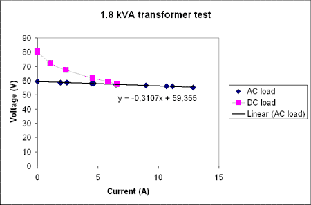
There was something strange going on when I measured the transformer last time, and since that I've gotten a few pointers from visitors to the blog and the CAD_CAM_EDM_DRO list.
I now did a test without the inrush current-limiter, and it does make a difference. It is rated for 8 A continuous current, but apparently it limits current much before that...
Now the 'AC load' line is measured by hooking up resistive loads to the secondary windings (no rectifier or caps), and it shows a series resistance of about 0.3 Ohms, or similar to what can be measured with a multimeter over the secondary windings. So at least the transformer seems to be working.
Then I hook up the secondary to the diode bridge and the caps and connect the same set of resistive loads as before. That's the 'DC load' measurements above. There again I see a big drop in voltage at first that then levels off somewhat. For the points above 5 A current the voltage drop is around 2 V per amp, or about a 2 Ohm effective series resistance. Also, the transformer does not emit any sound at all during the AC test, but now with the rectifier and caps when I load it up there is a slight 'humm' sound(probably 50 Hz and its harmonics).
I wonder if that 2 Ohm is typical or if there still is something strange going on? (could the rectifier bridge be too small? Anything wrong with my 4x 10 000 uF 100 V electrolytic caps?)
I tested this with one bridge rectifier GBPC5004 rated at 400V/50A and another one, a GBPC5010 rated 1000V/50A, but the results are the same. Looking with an oscilloscope at 6 A load at the DC voltage there is about 1.4 V of ripple.
David LeVine had a good point in the previous post which might just explain this. At relatively low load, "duty cycle" of transformer may be for example 10%. So if you draw 1Amp, transformer sees 10A load at 10% duty cycle. That would equal 10x larger voltage drop compared to pure sinusoidal load which appears always as 100% duty cycle load.
PFC circuit can be used to rectify AC more efficiently.