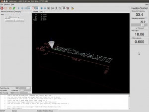
We hooked up the temperature measurement circuit and the PWM-amplifier to EMC today and tested PID-control of the extruder head temperature. The ini, hal, and xml files for this are here: temp_control_pid.tar
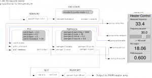
It's probably much easier to figure out the connections from the diagram below than to browse the text files. The square wave, which has a frequency proportional to the temperature, comes in on parallel port pin-13, and is connected to an encoder. The encoder has a velocity output which will be equal to the frequency of the square wave in Hz. This frequency is used as the feedback for a PID-component which compares the measured frequency against a set-point which is taken from a pyvcp slider. The pid output is used as an input to a pwm-generator, whose output needs an inverter, since the pwm-amplifier is active-low. The PWM is output on parallel port pin 9.
I wish there was a tool which would draw these HAL/pyVCP diagrams automagically from the source files. There is some work in that direction already: crapahalic and HAL with gschem.


for better circuit diagrams, see:
http://heartygfx.blogspot.fr/2012/11/repstrap-cnc-sous-linuxcnc.html