Update: this version of the component may compile on 10.04LTS without errors/warnings: frequency2temperature.comp (thanks to jepler!)
There's been some interest in my 2-wire temperature PID control from 2010. It uses one parallel port pin for a PWM-heater, and another connected to a 555-timer for temperature measurement. I didn't document the circuits very well, but they should be simple to reproduce for someone with an electronics background.
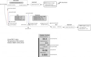
Here's the HAL setup once again:
The idea is to count the 555 output-frequency with an encoder, compare this to a set-point value from the user, and use a pid component to drive a pwm-generator that drives the heater.
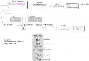
Now it might be nicer to set the temperature in degrees C instead of a frequency. I've hacked together a new component called frequency2temperature that can be inserted after the encoder. This obviously required the thermistor B-parameters as well as the 555-astable circuit component values as input (these are hard-coded constants in frequency2temperature.comp) . Like this:
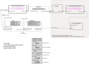
I didn't have the actual circuits and extruder at hand when coding this. So instead I made a simulated extruder (sim_extruder) component and generated simulated 555-output. Like this:
This also requires a conversion in the reverse direction called temperature2frequency. A stepgen is then used to generate a pulse-train (simulating the 555-output).
- The INI and HAL files for the simulated extruder, based on the default axis_mm config: simextruder
- frequency2temperature component: frequency2temperature.comp (install with: "comp --install frequency2temperature.comp")
- temperature2frequency component: temperature2frequency.comp (only for simulated setup, not required if you have actual hardware)
- sim_extruder component: sim_extruder.comp (only for simulated setup, not required if you have actual hardware)
"heartyGFX" has made some progress on this. He has a proper circuit diagram for the PWM-heater and 555-astable. His circuits look much nicer than mine!
The diagrams above were drawn with Inkscape in SVG format: temp_pid_control_svg_diagrams


I was wondering if you have created an M109 macro that is normally used in Slic3r to automate the process, in other words the Gcode will switch on the heater with M109 210 (210°c or what ever temp is required) and wait until the requested temp is reached before continuing to run the rest of the Gcode.