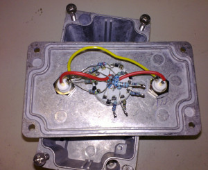
"Attenuator" is just a fancy word for voltage divider. This hack will not win many points for beauty:

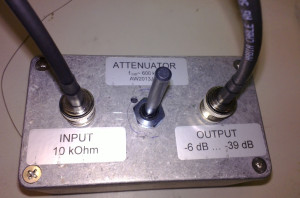
Enclosed in a box it looks nicer 🙂

This attenuator goes between two op-amp circuits where I figured the first circuit will be able to drive a 10 kOhm load, and the input impedance of the second circuit is high enough not to load the voltage divider too much.
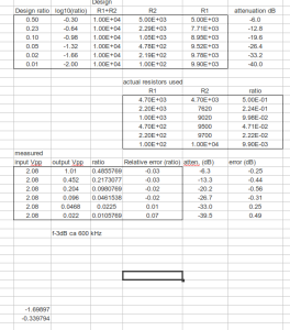
The back-of-the envelope design called for six voltage dividers with log-spaced attenuation between -6 dB and -40 dB. The input and output are connected to a 2-pole 6-position rotary switch that selects which voltage-divider is in use. The measured attenuation differs from the design by about 0.5 dB at most. For a large input-signal at the -6 dB attenuation setting the -3 dB bandwidth is about 600 kHz.
