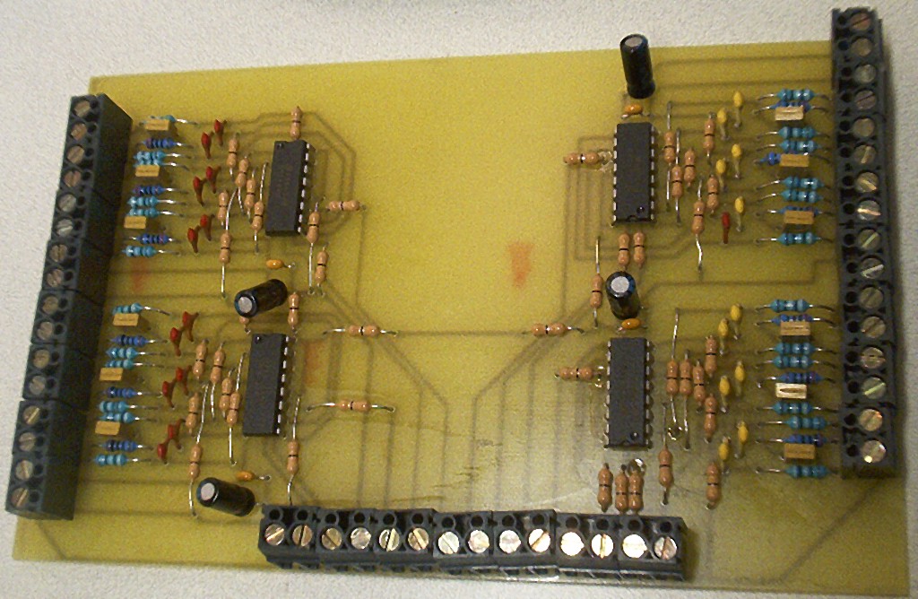
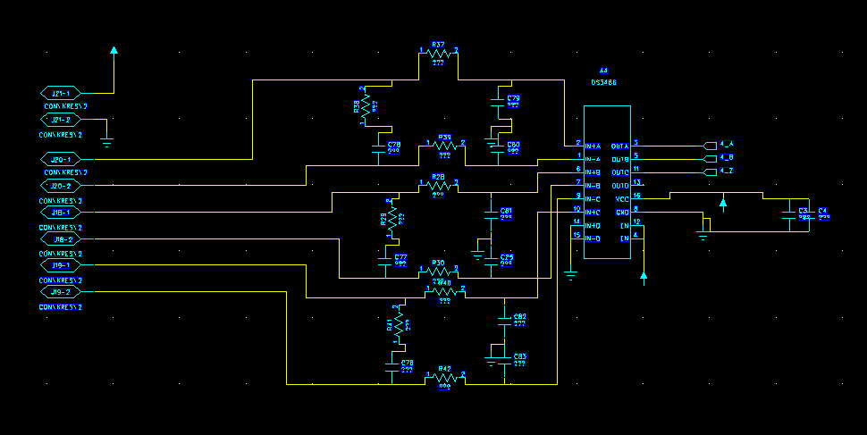
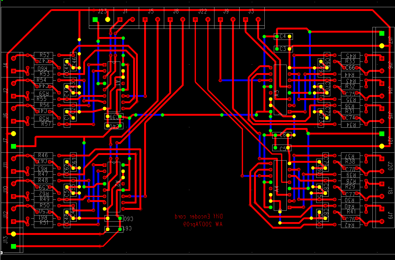
I threw together this board for decoding the differential encoder signals coming from the servos. I don't like etching two-sided PCBs, but I'm not sure I like this many zero-ohm jumpers either... It's basically four DS3486 ICs with input filters + a lot of connectors.
The circuit is borrowed from an IRF application note, second to last page of this document: http://www.irf.com/technical-info/refdesigns/dg-irmck201.pdf
Not very compact or cute, but hopefully functional...
Source: PADS PowerLogic schematic and PADS PowerPCB PCB-layout.


Anders, I was looking for the dc_servo_schematic that I downloaded from your site and can't find it again. Is that a work in progress?
There's a preliminary drawing at
http://www.anderswallin.net/sandbox/servo.pdf
which I also mentioned in a post to the EMC mailing list.
I'll post something better and more complete when the mill is actually running with the servos.
AW