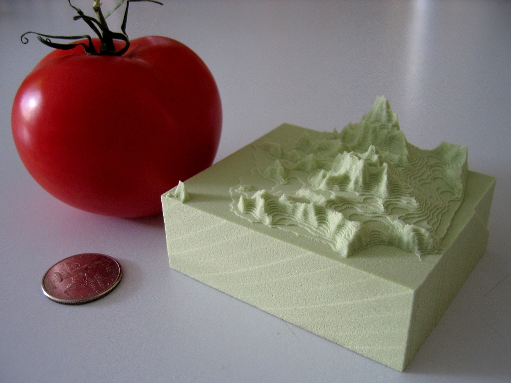
Dan Egnor sent me this nice example of bitmap-based toolpath generation, or 'pixel mowing'. It's a slightly exaggerated topographic relief of San Francisco machined in tooling board using a very simple 'lawn mowing' toolpath generator.
The explanation of how it works below is mostly Dan's, not mine.
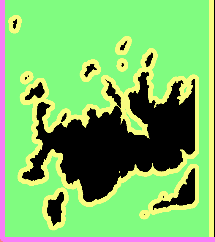
This is the input to the toolpath generator for one of the Z-slices.
black - material which must not be touched
green - to be removed, is safe (at least one tool radius from black)
yellow - remove if possible, is dangerous (within tool radius of black)
purple - has been cleared, is dangerous (machine limits or similar)
white - has been cleared, is safe, is not blue (below)
blue - this spot has been cleared, and is safe, but is within one tool radius of material that needs clearing (green or yellow)
Note that you don't see blue in either "before" or "after" images, it only occurs transiently. (In theory it could show up in "before" as area outside the workpiece.)
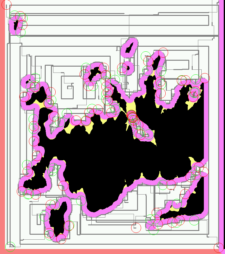
And this is the resulting toolpath. Green circles are plunges and red circles are lifts. The thick grey lines represent actual cuts, the thinner lines are rapid feeds.
The basic rule is that the tool *centroid* is only allowed to visit safe areas (green, blue, and white). Green and blue represent work to be done (safe areas that need visiting). Of course, as the tool moves, green changes to blue and white, and (some) yellow changes to purple.
The real trick is in efficiently tracking the "within tool radius of" zones (material to be cut, or material to stay away from). Every pixel keeps a count of how many pixels of each type ("nearby-blocking" or "nearby-cutting") are within one tool radius of that pixel. Whenever a value is changed ( e.g. the simulated tool moves and changes some points from "cut" to "clear"), every counter within the appropriate radius is updated.
That would be rather costly to implement directly, each simulated pixel move would require N^3 updates, if N is the diameter of the tool. Instead those counters are only kept as *differences* between each point and its neighbours. That means changing a point only requires updating the values along the *perimeter* of the radius surrounding that point, meaning that a simulated pixel move only requires N^2 updates, which makes things a lot more tractable (though it still takes the old laptop I use a couple minutes to complete the toolpaths for a 5" x 3" x 1.5" model at 1/256" resolution). Of course this means that the "color state" isn't directly accessible for a random pixel, but must be figured incrementally from neighboring values. Fortunately most operations don't access random pixels.
You would probably not want to cut metal with this kind of algorithm as there is no control over material removal rate or cutting forces, but for foam, tooling-board, or wood it should work ok.
Dan's program is written in C++ and available here (http://svn.ofb.net/svn/egnor/boring/), but it's not well documented.
We are standing by for a video of this kind of cutting!


This looks cool! I wish I understood this stuff a bit better..
Some time ago I actually thought about something like that, but couldn't figure out anything useful. This explanation was good, helps me to think.
Video would be really nice.
Cool!
Maybe the algorithm could be developed so that it allows machining the rest material with a smaller tool after the first pass. Maybe also some toolpath filtering could be added to make smoother movement in corners.