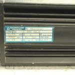
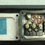
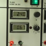
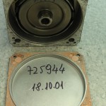
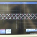
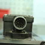
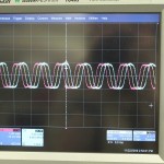
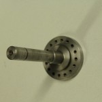
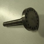
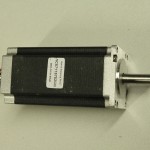
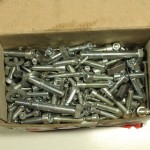
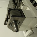
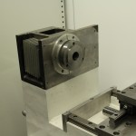
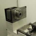
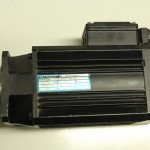
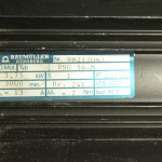
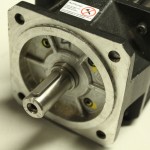
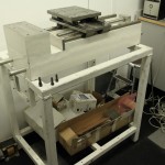
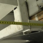
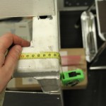
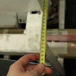
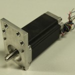
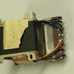
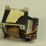
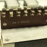
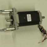
A closer look at the spindle-servo today. Googling for the model number does not immediately yield a datasheet, although I found a few similar-ish model numbers. The high-power connector is simple with U, V, W phases, Protective Earth, and +/- terminals for the solenoid brake. The brake opens at 24V and 0.67 A. The back can also be opened but doesn't reveal much more than an October 2001 manufacturing date. Hooking the scope to U, V, W and rotating the shaft with an electric drill produces some nice sine-waves. I'm not at all sure about the pinout of the encoder-connector, but looking at pairs 1/2, 3/4, and 5/6 seems to give something that could maybe be a resolver?
Category: CNC
JHQ Lathe
I've bought a cnc-lathe!
Well, it's not complete, more of a cnc-lathe project.
A fellow Finnish cnc'er "JHQ" started this project a few years ago, but as he now has a 5000 kg professional cnc-lathe and his own company, he hasn't had time/money to complete this project. There are many project logs out there with details of how the machine was designed and built:
http://cnczone.com/forums/showthread.php?t=27031
http://www.cnc-tekniikka.com/CNC-forum1/index.php?topic=121.0
http://www.robosota.fi/foorumi/viewtopic.php?t=935
http://www.devonparkour.com/ukcnc/forum/viewtopic.php?f=6&t=9
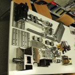
Some notes of my own, as I unpacked everything today.
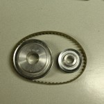
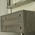
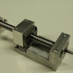
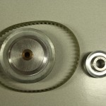
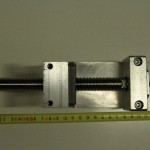
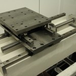
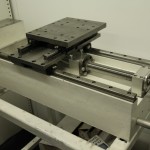
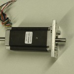
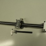
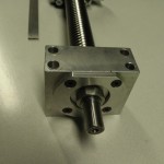
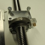
Stepper motors are NEMA23 size with 10 mm diameter shafts (ca 20 mm long). I will most probably not use stepper-motors but NEMA23-size brushless servos instead. The X-ballscrew is 16mm diameter with 4mm lead. It is 158mm long while the nut is 37mm long. That makes for a theoretical max travel of 121mm (enough?). The timing belt pulleys for both Z- and X-axes are type 21T5-36 and 21T5-21 or 21T5-16. That makes for a 1:1.7 or 1:2.25 reduction ratio. The Z-ballscrew is ca 30mm diameter with a 5mm lead (might be 0.2" also). It is 545mm long, the nut is 63mm long, theoretical travel 482mm.
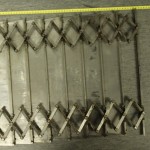
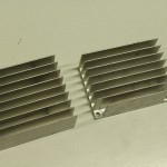
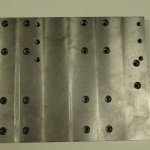
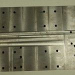
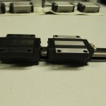
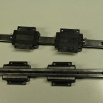
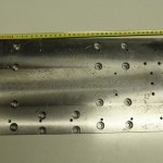
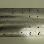
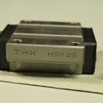
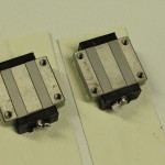
The chip-guard is ca 450-460mm wide and around 185mm long when fully compressed. It extends to much longer than required. The Z-rails are HSR25 type and the X-rails are HSR20 type (length 340mm). The Z-saddle-plate is 380x195x15.3mm. The X-saddle-plate is 275x227x20.4mm.
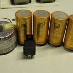
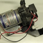
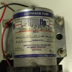
The coolant pump is rated as 24V/3.5A. There is a transformer with a 24V/3.5A secondary for powering the coolant pump.
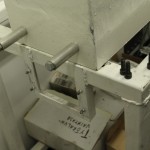
The spindle servo is rated at 1.75kW, 3000rpm, 13A, and 7Nm. The spindle servo axis is 19mm in diameter and ca 35mm long. The spindle itself is 45mm in outer diameter where the pulley for the belt-drive should attach. The chuck-holder is 100mm in diameter.
These images are also on picasa: http://picasaweb.google.fi/anders.e.e.wallin/JHQLathe2009_11_21#
Carbide-insert Lathe Tools
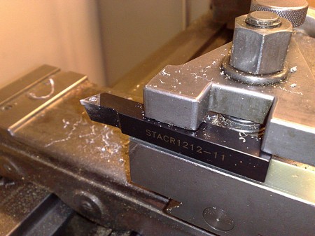
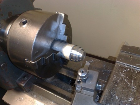
I got tired of sharpening dull high-speed steel tools, so tried some carbide-insert tooling today. Seems to work fine in brass and aluminium. Note ca 1.5 mm thick piece of PCB-material underneath tool which elevates the 12x12mm tool-holder to the center of the chuck (within maybe 0.1mm).
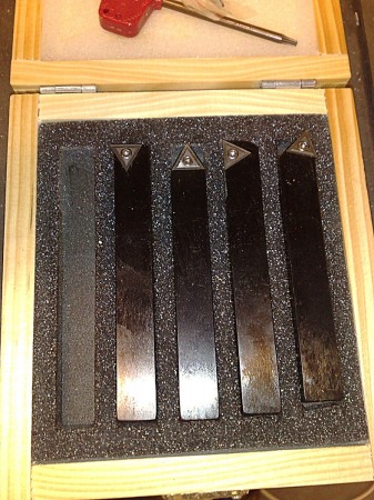
A set of five different tools with 12x12 mm holders. Not sure what all the different shapes are good for, but I'll find out eventually. Would still need a small tool that fits into a 12-13mm hole for internal turning.
Surface finish is better than before. The carbide inserts like high speeds, with our lathe that means running it at the max 1500 rpm for most of the time.
Learning VTK
I'm trying to learn how to render and animate things using VTK. This is the result of a python-script which outputs a series of PNG-frames. These are then converted to jpegs by this command:
mogrify -format jpg -quality 97 *.png
mencoder mf://*.jpg -mf fps=25:type=jpg -ovc lavc -lavcopts vcodec=mpeg4 -ac copy -o output.avi -ffourcc DX50
This should lead to the revival of my old Drop-Cutter code in the near future. This time it's going to be in C++, with Python bindings, and hopefully use OpenMP. Stay tuned.
Milling Steel
And here some pocketing in aluminium:
Anodizing aluminium
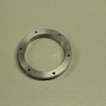
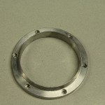
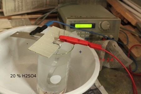
We thought all those aluminium bits the cnc-mill spits out needed to look all nice and pretty. So a test with some DIY-anodizing today. Following one of the many guides out on the interwebs (here and here) we mixed ourselves some 20 % sulphuric acid, inserted an aluminium plate which works as the cathode, and suspended the part to be anodized from an aluminum wire.
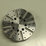
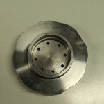
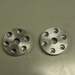
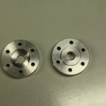
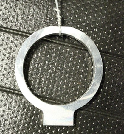
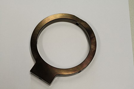
This was tested on these rings which hold the finder-scope on my telescope.
After about 30 min of anodizing with the current around 2 A the part was rinsed in water and then put into hot water containing black color used for coloring clothes. The part was then boiled in this solution for another 20 min. The guides tell me the oxide layer formed in anodizing is first very porous and will absorb the color, and while boiling the pores close leaving a less brittle oxide-layer and sealing the color within.
This wasn't too scary and the initial results look promising. More to follow later probably...
Mowing video moved
Jumpcut is closing, so I needed to move this video to youtube. This relates to my earlier posts here
http://www.anderswallin.net/2007/12/mowing-tactics/
and here
http://www.anderswallin.net/2007/06/an-emergent-spiral/
When I find time to work on this next, there are many ideas for improvements: How to specify only climb/conventional milling (allowing only the right or left side of the cutter to be used). Using a variable step length for the simulation. Simulating dynamics of the macing (controlling the tool with a trajectory generator with acceleration/speed limits etc). How to implement rapid feed between cutting moves? how to choose among many allowed starting points for the cut? Should this use an adaptive resolution model, like a quad-tree? How should G-code be output, a filter which outputs G-code within a specified tolerance of the simulated path would probably be best?
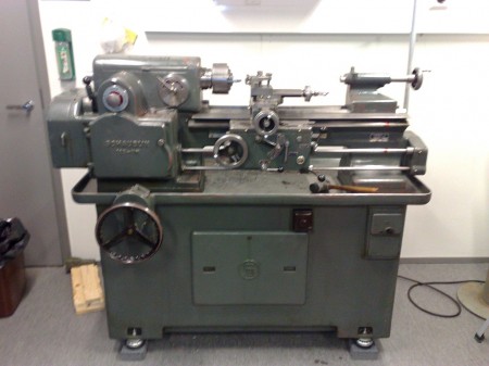
1949 Schaublin lathe
Servo setup with m5i20 and EMC2
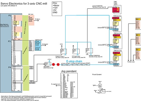
By popular demand, a schematic which roughly shows the electrical connections of our cnc-mill setup. Most of it fits inside one box (also shown here). The m5i20 I/O connectors are on the left, followed by the optoisolator cards. E-stop chain in the middle, servo-amplifiers and motors to the right. Jog wheel at the bottom. The small VFD board I made later is not shown.
Nikon TE-2000 objective holder in steel
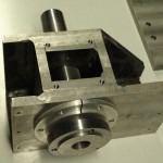
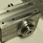
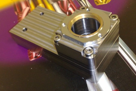
I'm fitting some more equipment around a Nikon TE-2000 microscope, and the stock objective turret is in the way. Machined this objective holder in steel yesterday.
