Yahoo the orienteering season 2017 has been opened!
Easy orienteering on a well-known area/map 😉 Still managed to be confused at #2 about the control-code, and then a small loop around #10.
Here's a tunable coil with an inductance between around 1.9 mH at minimum and 2.9 mH at maximum. The outer coil is around 200 turns of AWG16 wire around a 160mm diameter tube. The rotating inner coil is maybe 60 turns of AWG16 wire around a 110mm diameter 90mm length tube. The inner coil rotates on a 20mm solid rod with 10mm diameter holes through the ends for feeding the wires out. A small geared DC-motor rotates the rod.
Time signal reception with a long-wire antenna and a PA0RDT mini-whip antenna. HP89410A analyzer set to 50 Ohm input, 100 Hz span, 1 Hz RBW. The signals are from:
I wonder if they archive results on Zwiftpower forever: http://www.zwiftpower.com/race.php?id=3614 ?
Group-ride on the zwift mountain route today.

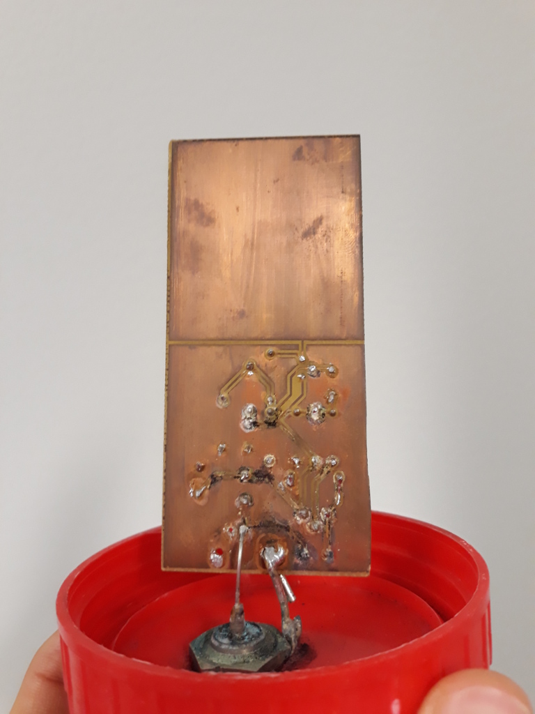
Antenna in a bottle installed on the roof today. Stay tuned for a future web-SDR...
An article, some theory, some notes on grounding, some comparisons,
There's also a modernized circuit by PA0NHC
Inspired by PA0NHC mini-whip, Jonathan Hare's Antennas for MSF 60 kHz LF, and Ferrite Sleeve Loop Antennas.
Seems to work quite well! This prototype shows about 140 pF of input(or parasitic) capacitance when the tuning capacitor is set to 0 pF. That could probably be improved on by better layout on a custom PCB.
Web-SDR located at Nastola
RF power amplifier of DCF77 modulated time-code transmitter.
1:8 frequency distribution amplifier based on LMH6702 and LMH6609 op-amps.
In particular the power-supply section using a common-mode choke, a Murata BNX025 filter, and low-noise regulators LT1963 and LT3015 seems to work quite well. I also used ferrites (2 kOhm @ 100 MHz) as well as an RC-filter on all supply pins. Perhaps overkill? Performance with the intended AC/DC brick is still to be verified.
Measurements around 10 MHz show a 1 dB compression at over 14 dBm and an IP3 of around 27 to 30 dBm. The gain extends beyond 100 MHz with some gain-peaking.
Some measurements of residual phase-noise with a 3120A phase-meter, at 10 MHz. My earlier distribution amplifier required shielding with aluminium foil as well as powering from a lead-acid battery to achieve a reasonably quiet phase-noise spectrum. These measurements were done with lab power-supplies for +/-12 V to the board and without any shielding.
Finally some measurements of gain vs. frequency with a Rigol spectrum analyzer.
A new pulse distribution amplifier for 1PPS distribution.
The input is fed to a LT1711 comparator triggering at 1.0 V (set by reference ADR423). This edge is buffered by 74AC14 before 1:8 fan-out to output-stages with three 74AC04 inverters in parallel driving the outputs.
Preliminary measurements show around 200ps channel-to-channel propagation skew - to be improved on by further trace-length matching or tuning. More measurements to follow.