Leap second time-stamps for leap-seconds.list

This function generates time-stamps in the format used in leap-seconds.list (on e.g. NTP or PTP servers). The format is integer seconds since 1900-01-01T00:00+00.

import datetime
import pytz
 
 
def generate_ntp_timestamp(year,month,day,hour,minute,second):
    t = datetime.datetime(year,month,day,hour,minute,second,tzinfo=pytz.utc)
    #NTP leap-seconds list wants seconds since 1900
    epoch_start = datetime.datetime(1900,1,1,0,0,0,tzinfo=pytz.utc)
    delta = t-epoch_start
    delta_s = delta.total_seconds()
    return int(delta_s)
 
 
# test that this generates OK values.
# from existing leap-seconds.list
# 2918937600	27	# 1 Jul 1992
# 2950473600	28	# 1 Jul 1993
# 2982009600	29	# 1 Jul 1994
# 3029443200	30	# 1 Jan 1996
# 3076704000	31	# 1 Jul 1997
# 3124137600	32	# 1 Jan 1999
# 3345062400	33	# 1 Jan 2006
# 3439756800	34	# 1 Jan 2009
print "1 Jan 2009: ", generate_ntp_timestamp(2009,1,1,0,0,0)
print "1 Jan 2006: ", generate_ntp_timestamp(2006,1,1,0,0,0)
print "1 Jul 1997: ", generate_ntp_timestamp(1997,7,1,0,0,0)
#output:
#1 Jan 2009:  3439756800
#1 Jan 2006:  3345062400
#1 Jul 1997:  3076704000

PICDIV frequency divider

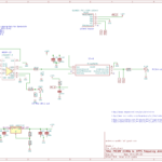
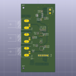
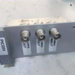
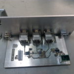
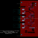
I put together a PICDIV frequency divider for use with a Rubidium clock.

I used an LTC6957-3 to convert the 10 MHz sine-wave from the clock to a CMOS logic signal (square wave). The LTC6957-3 has two outputs, one is routed to a BNC connector output, the other is used as the clock for a PIC12F675. The PIC runs pd09.asm which outputs a 20 us long pulse every second - i.e. it divides the 10 MHz input frequency by 1e7. The PIC is programmed through a 5-pin 100 mil ICSP header.

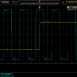
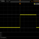
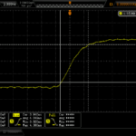
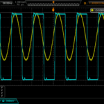
Here are some test-signals with a SRS PRS-10 as the source, and recorded on a Rigol scope.

The outputs behave as expected, but the 1PPS from the PIC is only 700 mVpp into 50R - a bit low. When terminated to 1 MOhm the rise-time is much worse so this is best avoided. Perhaps a buffer or level-translator would be a good addition.

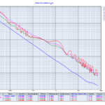
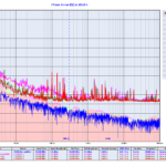
Finally phase-noise measurements on the 10 MHz CMOS output, performed with a 3120A phase-noise probe.

I tried shielding the circuit with aluminium foil and powering it from a +12 VDC lead-acid battery - however the three measurement runs look roughly similar. Perhaps the LM317 regulator is not a great choice here, and both the LTC sine-to-square chip and the PIC should have more bypass caps and decoupling (inductors, ferrites?). In any case the phase-noise is 10-20x better than the measurement noise from a typical counter (SR620 or 53230A), so any issues only show up with high-end phase-noise probes.

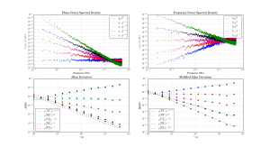
Five colours of noise

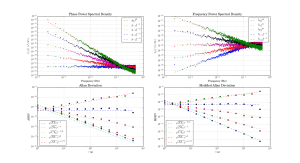
Update: now with the colours matching in all graphs:

colorednoise

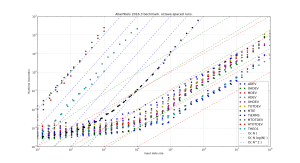
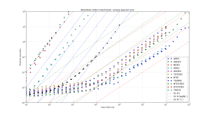
Time-series generated with colorednoise (following Kasdin&Walter), power-spectral-densities and Allan deviations computed with allantools, and compared to theoretical predictions in IEEE1139-2008.

colorednoise

The PSD lines and MDEV lines seem spot-on, but are the ADEV lines systematically a bit low?

Code here: example_noise_slopes.py