Rigol DS2072A upgrade

Short notes on Rigol DS2072A upgrade following bineteri's step-by-step post.

  1. Use Rigol Bildschirmkopie LAN/USB for making a memory dump over LAN/SCPI: ":SYST:UTIL:READ? 1,33554432"  this results in a 32 Mb memory dump saved as "DS2072A.bin"
  2. Use rigup 0.4 in two stages to generate keys:
    1. "rigup scan DS2072A.bin > EC-keys.txt"
    2. "rigup DS2072A DS2072A.bin > Options.txt"
  3. Read Options.txt and install the wanted key over SCPI: ":SYST:OPT:INSTALL A_KEY_FROM_OPTIONS_WITHOUT_DASHES"

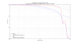
Frequency response before and after:

rigol_DS2072A_upgrade

Python code for plot:

1
2
3
4
5
6
7
8
9
10
11
12
13
14
15
16
17
18
19
20
21
22
23
24
25
26
27
28
29
30
31
32
import matplotlib.pyplot as plt
import math
 
# rigol ds2072a frequency response test
# AW2015-12-28
 
bf=[10, 20, 40, 60, 70, 80, 100, 130, 160, 200, 250, 300, 400, 500, 600, 700, 800, 900, 1000]
before=[1008, 992, 944, 880, 848, 808, 728, 624, 560, 456, 396, 332, 224, 100, 25, 18, 1.5, 1, 1]
 
af=[10, 20, 40, 60, 70, 80, 100, 130, 160, 200, 250, 300, 350, 400, 450, 500, 550, 600, 700, 800, 900, 1000 ]
after=[1000, 984, 984, 984, 992, 976, 976, 944, 928, 904, 888, 856, 760, 656, 556, 308, 20, 30, 40, 1, 1.5, 2]
 
# for comparison RC-filter response for 70MHz and 300MHz
rc70 = [ 1000.0 / math.sqrt( 1+ pow( f/70.0, 2 ) ) for f in bf]
rc300 = [ 1000.0 / math.sqrt( 1+ pow( f/300.0, 2 ) ) for f in bf]
 
plt.figure()
plt.loglog(bf, before,'b',label='Before')
plt.loglog(bf, rc70 ,'b--',label='70 MHz RC-filter response')
 
plt.loglog(af, after,'r',label='After')
plt.loglog(bf, rc300,'r--',label='300 MHz RC-filter response')
 
 
plt.title('Rigol DS2072A update, AW2015-12-28\nSignal generator: HP8647A (+3.8 dBm) into CH1 50 Ohm DC-coupled')
 
plt.ylabel('CH1 Vpp (mV)')
plt.xlabel('Frequency (MHz)')
plt.grid(True, which="both")
plt.ylim((1,1100))
plt.legend(framealpha=0.6, loc='lower left')
plt.show()

Frequency Distribution Amplifier, v2 simulations

I wasn't entirely happy with my frequency distribution amplifier prototype measurements, so I decided to do some SPICE simulations.

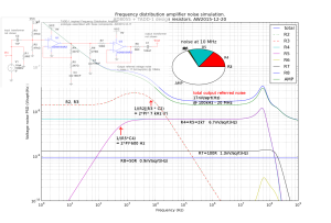
Here is a circuit close to the original TADD-1 design, configured for a voltage gain of 2, which when loaded with 50R corresponds to unity gain or 0 dB.

fda_noise_ad8055_with_comments

The main contribution to the noise floor at 10 MHz is by the AD8055 op-amp (roughly 3/4ths), with the gain-resistors R4 and R5 also contributing (roughly 1/4th). The simulation gives an output-referred noise-floor of 17.4 nV/sqrt(Hz) between around 100kHz and 20MHz. At low frequencies the 1/f noise of the op-amp dominates. The large 47k bias-resistors R2 and R3 are not bypassed/filtered in this design and they contribute significantly at low frequencies.

17.4nV/sqrt(Hz) is -142 dBm/Hz. This is a one-sided spectrum so we subtract 3 dB to get a single-sideband number, and then another 3 dB since noise is divided equally into AM and PN. This gives a best-case PN of -148 dBc/Hz for a 0 dB input/output power. In my measurements I got about -157 dBc/Hz with +7 dBm output.

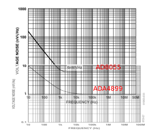
fda_noise_opamp

The v2 design uses the ADA4899-1 op-amp instead of the AD8055. This improves the op-amp input voltage noise floor from 6 nV/sqrt(Hz) to 1 nV/sqrt(Hz)  while also reducing the near-DC voltage noise by more than ten-fold.

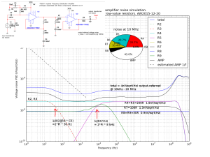
fda_noise_ada4899_with_comments

The simulation for the ADA4899-1 design shows an output-referred noise floor of 4 nV/sqrt(Hz) from 10 kHz to 20 MHz. This corresponds to about -155 dBm/Hz, a 12.7 dB improvement over the original design. The SPICE model for the ADA4899-1 does not include 1/f noise so I have estimated it with a dashed line. I have tried to minimize the resistor noise with reduced resistance values for the gain-setting resistors R4, R5, and a bypassed (C5) 'T'-circuit for the DC-bias (R2, R3, R9).

The theoretical PN floor with 0 dBm signal is now -161 dBc/Hz (again 13 dB better than for the original design).

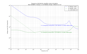
Here is a figure that compares the two simulations:

fda_noise_comparison

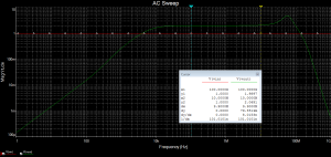
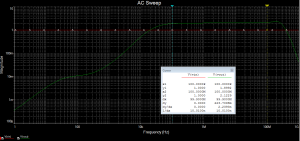
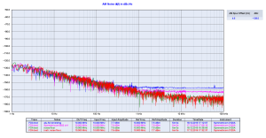
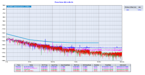
These figures show an AC sweep response for the SPICE simulations:

fda_v1_ac_sweep  fda_v2_ac_sweep

Further ideas and ToDo:

  • What is the limit for reducing values of R4 and R5? Power-dissipation, current-draw from the op-amp?
  • Reduce value of R7 - do we even need it.. (improves isolation between output stages?)
  • Replace R9 with an inductor - BUT it creates a resonance with C5 that needs to be damped - probably not worth it.
  • Improve on the powersupply schematic in the prototype. Spurs were big with a SMPS +12VDC supply.
  • Do PSRR simulations? Does that give different optimization goals for the DC-bias circuit?
  • Find an even better op-amp?
  • Where do we find a good SPICE model for ADA4899-1? The one I am using has a realistic AC gain response but unrealistic noise model near DC. There is an alternative on the analog.com website with realistic 1/f noise behaviour but infinite AC gain bandwidth!!??

Constructive comments are welcome!

Spectrum Analyzer or Phase Noise Probe for Phase Noise measurement?

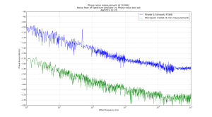
Update 2016-01-14: Added noise floor of Symmetricom 5115A:

phase_noise_floor_10MHz_2016-01-14

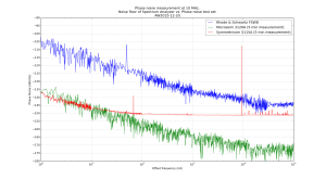
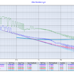
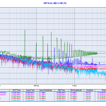
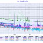
The question of using a general purpose Spectrum Analyzer vs. a dedicated phase noise test set for measuring phase noise came up on the EEVBlog forum. Here are two noise floors for 10 MHz phase noise measurements measured recently. One with a R&S FSW8 spectrum analyzer and the other with a Microsemi 3120A phase noise probe. The 3120A noise floor improves  by maybe 10 dB in a longer duration measurement (e.g. hours instead of minutes). On the other hand the SA can measure phase noise out to at least 1MHz offset frequency and at any (I think?) carrier frequency up to several GHz.

sa_vs_test-set_for_phasenoise

Frequency Distribution Amplifier - first tests

Update 2015-12-18: Things improved quite a lot by simply wrapping the board in aluminium foil!
alufoil_and_battery_AMalufoil_and_battery

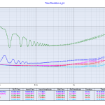
The amplifier phase noise floor is now at around -156 dBc/Hz while the 6502 is at -163 dBc/Hz. The AM noise numbers are similar.

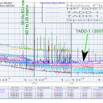
Original post 2015-12-17: I put together a first prototype (only one output channel) of my TADD-1 inspired frequency distribution amplifier. Preliminary schematic here.

I compared the prototype board to two commercial distribution amplifiers: an SRS FS710 (quite awful) and a Symmetricom 6502 (very good). I also compared my new data with John Ackermann's measurements from 2007.

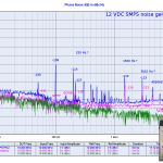
The new board showed ugly spurs at 50 Hz and harmonics using an el-cheapo wall-wart 12 VDC SMPS, so I also tried it with an "ultra-low noise DC-source" a.k.a 12 V lead-acid battery.

NTP Timestamp

1
2
3
4
5
6
7
8
9
10
11
12
13
14
15
16
17
18
19
20
21
22
23
24
25
26
import datetime
import pytz
 
 
def generate_ntp_timestamp(year,month,day,hour,minute,second):
    t = datetime.datetime(year,month,day,hour,minute,second,tzinfo=pytz.utc)
    #NTP leap-seconds list wants seconds since 1900
    epoch_start = datetime.datetime(1900,1,1,0,0,0,tzinfo=pytz.utc)
    delta = t-epoch_start
    delta_s = delta.total_seconds()
    return int(delta_s)
 
 
# test that this generates OK values.
# from existing leap-seconds.list
# 2918937600    27    # 1 Jul 1992
# 2950473600    28    # 1 Jul 1993
# 2982009600    29    # 1 Jul 1994
# 3029443200    30    # 1 Jan 1996
# 3076704000    31    # 1 Jul 1997
# 3124137600    32    # 1 Jan 1999
# 3345062400    33    # 1 Jan 2006
# 3439756800    34    # 1 Jan 2009
print "1 Jan 2009: ", generate_ntp_timestamp(2009,1,1,0,0,0)
print "1 Jan 2006: ", generate_ntp_timestamp(2006,1,1,0,0,0)
print "1 Jul 1997: ", generate_ntp_timestamp(1997,7,1,0,0,0)

y-cruncher

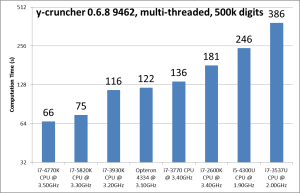
I ran y-cruncher on a number of machines. Note the logarithmic y-axis. Lower is faster.

y-cruncher_results

  • i7-3537U, 2.5 years old Lenovo yoga laptop. Runs hot. Time to upgrade?
  • i5-4300U, ~1 year old work laptop, HP ultrabook. Runs much cooler.
  • i7-2600K, 3+ years old home desktop
  • i7-3770, 2.5 years old work desktop
  • Opteron 4334, Del R515 server, 1? year old.
  • i7-3930K, computing machine at work, 3+ years old
  • i7-5820K and i7-4770K newest lab computers, both 1 year old.

Meinberg Lantime M600

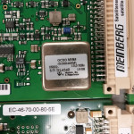
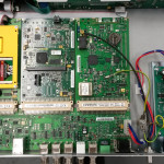
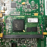
Here's a peek inside a Meinberg Lantime M600 PTP/NTP server. It follows the same modular design as the Lantime M300 with the GPS receiver on the right and the computer-board to the left. The new thing is a Time Stamping Unit (TSU) in the middle.

The TSU (by Toradex) seems to be built in a memory-stick form factor (SODIMM?) around a Marvell 88ap270m chip (PXA270 processor?). Maybe it's a Toradex Colibri PXZ270?

Frequency Distribution Amplifier plans - a.k.a. SMD-TADD-1

We need a number of frequency distribution amplifiers in the lab. Let's not reinvent the wheel but rather do a face-lift for the TADD-1. John Ackermann has phase noise measurements on the TADD-1 and TvB has temperature coefficient results on the TADD-1.

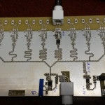
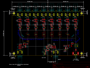
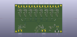
Here's a draft design for an SMD version of the TADD-1 frequency distribution amplifier. The plan is for a 2-sided 180 mm x 110 mm PCB. Two of these could be mounted side by side in a 1U 19" enclosure to give 2x8=16 outputs on the front panel. If a companion pulse distribution (1-PPS) board is built, the output at the back of this board can be used to drive a PICDIV on the pulse-distribution board. This gives 8 frequency outputs and 8 pulse outputs on a 1U 19" panel. The 2-pin connector at the DC-input can be used to power the other board in the same enclosure.

smd_tadd-1_draft_pcb smd_tadd-1_draft_pcb_3dview

Comments? Suggestions?

  • What causes phase-noise (drift) below 1Hz offset frequency in this graph?
  • The original TADD-1 used a MAX477 and the update in 2007 used an AD8055. Are there newer and better op-amps?
  • We need a good low-noise linear regulator circuit (lower right corner). Suggestions? (what's inside an Abracon ABPSM-ULN-A?)

PDF files: