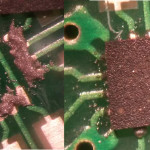
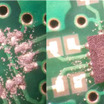
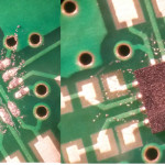
0.5mm pitch SMD parts with solderpaste

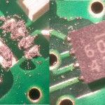
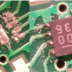
I soldered some quite small SMD parts today using solderpaste and a Hakko FR-810 hot-air rework station.

The smaller part is an 8-pin 2.0 mm x 2.0 mm MLF-8 packaged logic buffer. 0.5mm pin pitch. See page 17 over here.

The large part is a 14-pin 2.5mm x 2.5mm UQFN-14 packaged op-amp. Also 0.5mm pin pitch. Dimensions and footprint available here.

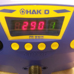
I had to rework one chip manually with a soldering iron because I applied too much solderpaste. Otherwise things seems to have gone smoothly. I applied the solderpaste manually using two disposable scalpels - getting the amount and location of solderpaste right took quite a long time. I then positioned the chip on the footprint and applied hot air. On the FR-810 I used the lowest air-flow setting "1" and a temperature of 290 C. When the solderpaste melts it pulls the chip into position if things go well.
KiCad footprints now on GitHub

I've created a GitHub repository for my KiCad footprints

https://github.com/aewallin/awallinKiCadFootprints.pretty

Maybe some day schematic symbols will also follow this foolproof convention of

  • directory <-> library
  • file <-> part

ToDo: polish up some of the footprints, check if they adhere to the Kicad Library Convention, and try to get them included in the official libraries.

Iltarastit Postintaival

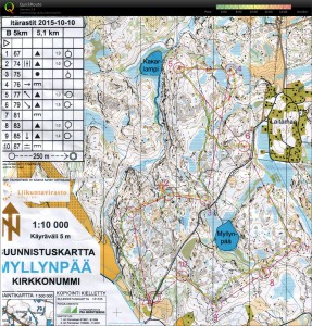
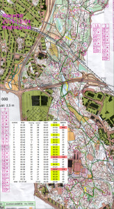
Sprint-like course in Helsinki central park. 23 legs over 7 km is about 300 m per leg on average.

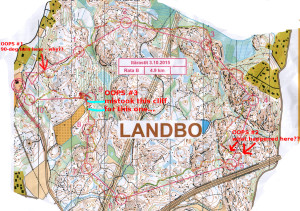
Three-four smaller and larger mistakes.

  • after a good start at #1 I zigzag towards #2 via the wrong hill. maybe +1min
  • down from #3 I take the wrong path to the bigger road. maybe +1min
  • towards #14 I should have taken the same path as on the #9-#10 leg but instead make a loop to the right. +2min at least
  • Out of #18 I first have the map 180-degrees wrong and take a few steps south before realizing I should go north. Then I read the #6-#5 line for a while before realizing I should go to #19. Crossing lines like this are always dangerous! Maybe +2min and the worst split.

2015-10-04_ir_postintaival_qr

Meinberg Lantime M300

Following Dave's advice here: "Don't turn it on - take it apart!"

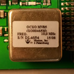
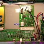
Meinberg Lantime M300 - Multi Reference NTP server. This server works as stratum-1 using a number of different input signals such as GPS, 1PPS, 10MHz, and IRIG/Timecode.

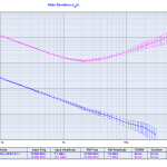
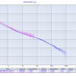
The loop time-constants seem to be very long, since the ADEV plot does not change much (at least not immediately) when connecting or disconnecting e.g. the 1PPS or 10MHz inputs. If I would be more patient I would measure it free-running and with all the different stratum-1 input signals for a few days each - that would maybe show some interesting things about how the internal OCXO is locked to the reference inputs. My assumption would be that IRIG would produce the worst ADEV, GPS second worst, 1PPS quite good, and the 10MHz input should produce an excellent ADEV with the shortest lock time-constant.

Microsemi/Symmetricom 3120A noise floor

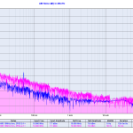
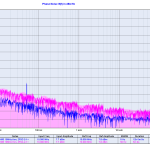
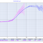
This was measured by taking a H-maser 10MHz signal (output from a frequency distribution amplifier) and splitting it in two for the 3120A REF and DUT channels with a ZFSC-2-1+ passive splitter.

The first measurement is with 50 Hz bandwidth and a duration of 5 minutes. The second measurement is at 5 Hz bandwidth and ran overnight for 12 hours.

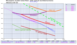
Here's the ADEV plot with some typical performance-curves added.

floor_with_comments

Data from:

SRS FS710 noise measurement

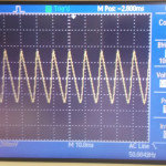
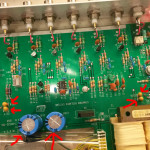
Update: changing the main electrolytic capacitors as well as the tantalum caps around the 7805/7905 voltage regulators did not help. There is still about 600 mVpp of ripple on the +/- 13.9 VDC inputs to the regulators.

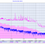
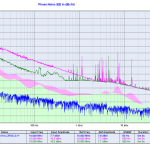
Here's a noise measurement on an old second-hand SRS FS710 distribution amplifier. I wonder if the excessive noise at 50 Hz and harmonics is within spec or a result of old age?

Measurement setup: 10MHz signal to a Mini-Circuits ZFSC-2-1+ splitter, one branch to 3120A REF-input, the other branch to the FS710 input, and FS710 output1 to the 3120A DUT input. Noise floor was measured with the same setup but bypassing the FS710.

White Rabbit Switch noise measurement

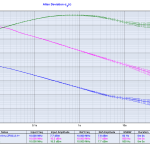
I measured the CLK2 10 MHz RF-output of two White Rabbit switches with a Microsemi 3120A. The results are similar to previous results with ADEV(1s)=1.5e-11.

When phase-locked to an external reference clock the long-term stability is obviously much better than when free-running, but for small tau, or high offset-frequency in the phase noise plot, the free running oscillator is actually better.