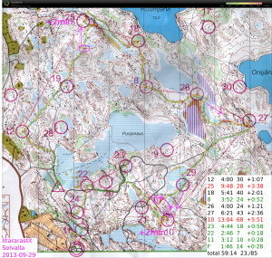
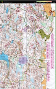
#12 OK
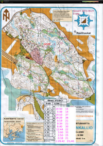
#25 should have run straight north into the control circle from the cliff, instead veered right and circled round
#18 felt OKish but the descent down the steep cliff was apparently slow and the split isn't great.
#8-#26 OK
#27 straight over the swamp would probably have been faster
#10 drifted into the swamp close to #29, maybe +1 min there. After I saw #29 I ran too much north and going down the hill didn't know at which cliff I was. Found #10 mostly because of other runners.. Worst split.
#23-#22-#11-F Some orienteering to reach the road before #23 but then just mainly running strength required. Not much lost on the three last legs 🙂
Itärastit, Landbo
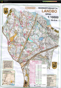
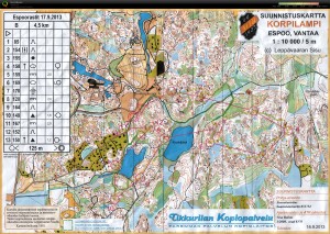
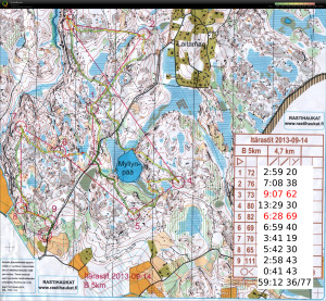
#1-#2 OK at easy speed
#3 small hook inside the control circle
#4 best split and direct route, but very slow going up the steep hill
#5-#6-#7 OK
#8 gave advice to someone just before the control, then ran past control myself until I stopped at two big rocks. worst split.
#9 from the bigger road I missed the path I wanted to take (blue line), and had to find it through the woods instead.
#10-#11-#12-#13-#14 more runners both in front and behind on these controls. Nothing special to report on.
NTP shared-memory refclock driver for White Rabbit SPEC
I've been playing with White Rabbit hardware at work. White Rabbit uses a combination of SyncE and PTP to perform very precise (<1 ns) time-distribution.
The standard low-precision way to distribute time is NTP. I hacked together a very experimental "Type 28" NTP refclock driver that reads the WR-time from SPEC shared memory and writes it to another location in shared memory where NTP expects it. Code over here: https://github.com/aewallin/ptp2ntpd
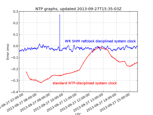
The graph shows system clock variations compared to WR-time (which we assume is very accurate) for a computer with the WR-refclock driver enabled (blue trace, minpoll 16 s), and another computer where the system clock is kept on time using standard NTP (I just added some servers to ntpd.conf, no other settings changed from default Ubuntu 12.04LTS). The WR-disciplined clock stays within maybe 50 microseconds with no net drift during the ~9 hour measurement, but the trace is quite jumpy. The NTP-disciplined clock wanders around much more (300 us) but the trace is smoother.
Agilent 34901A and 34907A breakout boards
Update 2015-09-16: Csaba Toth sent a picture of his front-panel for these breakout boards. Very nice finish with text/graphics on the 19" rack panel!
Update 2015-05-15: Files for PCB manufacturing: top, bottom, outline Gerber files, and Excellon drill files.
When opened with e.g. gerberview they should look like this:
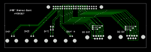
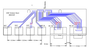
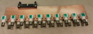
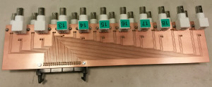
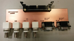
 The connector placement is shown here (sorry I don't have a drawing for the one with 20 BNC connectors):
A frustratingly large portion of any electronics or control system build has to do with cables and connectors. So here we go...
I'm using an Agilent 34970A datalogger/switch, which is a 6.5 digit (~22 bit) multimeter that takes up to three plug-in modules with various functions.
I'm using one 34901A module for 20 channels of DC voltage inputs. On the module there are 40 screw-terminals for these voltages which I have connected to a 40-pin ribbon cable that connects to this breakout board with 20 BNC connectors. Our PCB-mill can do 300mm long PCBs, which is just long enough for this board if the BNC connectors are interleaved on different sides of the board. Mounting BNC-connectors right next to each other on the same side is bad idea anyway as the connectors on the cables will not fit that closely. It should be possible to mount the whole thing in a 1U 19" rack panel.
For controlling the TEC drive I need analog outputs, provided by a 34907A module. Again I'm using a 40-pin ribbon cable from the screw-terminals on the module, and the breakout board has four BNC connectors: Two DAC outputs, one counter input, and a gate input for the counter). Additionally there are two 8-bit digital I/O ports which are routed to two DB9 connectors on the breakout board.
TEC Drive in enclosure
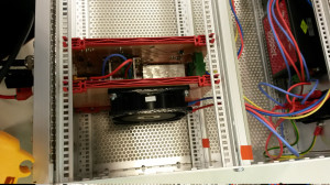
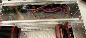
The TEC drive I have been working on is now mounted as a plug-in card in a 3U 19" rack enclosure like this:
The card next to the TEC drive holds an 80 mm fan which helps cool the heatsinked linear regulators and the linear H-bridge that drives the TEC.
The back of the 19" rack enclosure holds two TRACO POWER PSUs that produce +/-5 V at max 4 A and +/-15 V at max 667 mA. An IEC power-entry module containing the IEC-connector, a fuse, and a power switch is visible far right. Far left is a small PCB for distributing +/-15 V to other cards in the same enclosure.
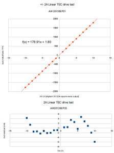
Added cooling allows testing the drive at the max input level of +/-10 V, which should produce (roughly) an output of +/-2 A.
The output current follows 179 mA/V * Vin + 1.8 mA with a maximum nonlinearity of about 6 mA (0.3% of full-scale). Despite the fan-cooling the transistors still get quite hot and staying below 1 A output in continuous operation is probably a good idea.
Itärastit, Salmenkallio
Espoorastit, Serena, night-orienteering
Iltarastit, Pirttibacka
Quite tired legs today...
#1-#2-#3 OK with a bit conservative route to #3
#4 the plan was to run west until I see the blue wet area and then turn left for the control. But the swamp never appeared and this required some re-location + searching.
#5-#6 OK
#7 difficult control in a very detailed area.
#8 probably distracted by the extra time spent at #7 I also made a mess out of #8...
#9-#10-#11-#12-#13-F OK but not great.
Octree simplification by QEFs
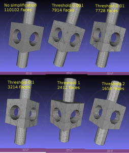
Dual contouring uses a quadratic-error-function (QEF) to position a vertex inside each octree-node (cube) where the implicit distance-field that defines our geometry changes sign. The vertex is positioned so that the QEF is minimized. This allows for an octree simplification strategy where we combine all the QEFs of the eight child-nodes, and see if we can replace the eight vertices they define with with a single vertex one level up in the octree.
This image shows the dual contouring code run on the same input data with various levels of simplification. Even a small threshold value of 0.001 reduces the number of triangles more than ten-fold. Too large a threshold produces jagged edges. Note that dual contouring of the original dataset where each leaf-node is at the same (maximal) depth of the tree produces only quad polygon output. When we simplify and collapse some nodes to non-maximal depth the algorithm also produces triangles - where a collapsed node is adjacent to nodes deeper in the tree.
