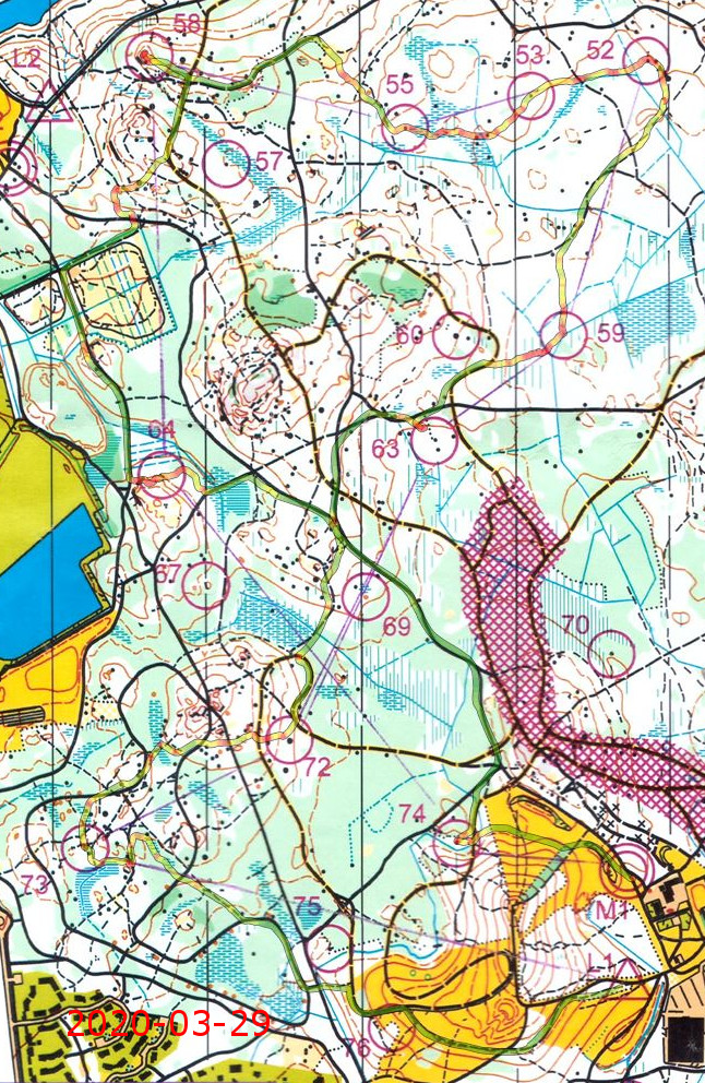
Orienteering season 2020 opened. No arranged events, just controls in the forest without timing or punching.
Extra bends/loops just before 73 (nerves on the first control?) and after 58 - otherwise mostly ok. No compass! Around 56 minutes.
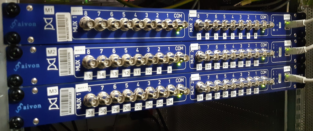
Just installed three of these 1U dual-1:8 RF-mutliplexers in the lab to make a 40-channel 1PPS measurement system. These are built by Aivon.
Time will tell how robust these are and if there are any failures in continuous use... Initial results from the field are good however.
We connect these in a depth-2 tree. One 1:8 mux is the top-level switch, with the remaining 5 providing 40 input-channels. This easily expands to 64 channels by adding one more 1U box. Beyond that I guess a depth-3 tree connection is required.
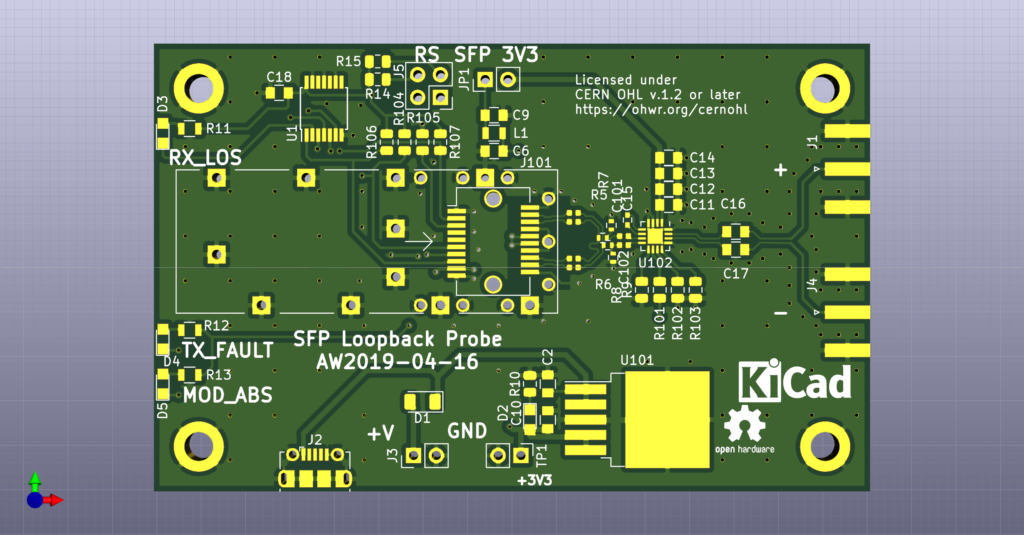
A simple SFP loopback board that loops back any received signal on the SFP RX-pins to the TX-pins. There's a voltage divider probing the signals, and an ONET1191P limiting amplifier provides amplified differential outputs, for probing the signal going through the SFP.
https://github.com/aewallin/SFP-Loopback-Board
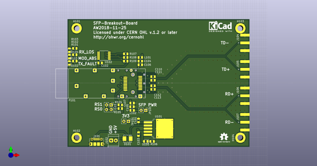
Designed in 2018, but only now uploaded to github, a simple SFP breakout board for playing around with SFP or SFP+ transcievers.
In contrast to earlier boards, this one has no op-amps or transformers on the TX/RX lines, and bandwidth seems to be good enough for 1Gbit/s at least.
https://github.com/aewallin/SFP-Breakout-Board
For the simple 'one-inch-photodetector' with a Hamamatsu S5973 photodiode, OPA657 op-amp, and 10 kOhm feedback-resistor the predicted noise-floor and signal output is fairly easy to compute, from a simplified schematic like this:
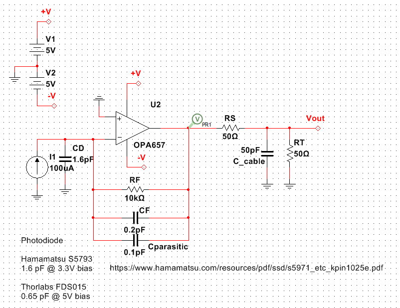
The photodiode is modeled as a current-source and adds some source-capacitance (in addition to the op-amp input capacitance). The board and components have some parasitic capacitance over RF, and additionally CF is chosen large enough for stability (no self-oscillation). A 50-ohm series resistor couples the signal into a coax to the spectrum-analyzer or scope.
For some (yet unknown..) reason I need to dial-down the GBWP of the op-amp to about half the datasheet value of 1.6 GHz - only then do I get good agreement between the predicted and measured spectra:
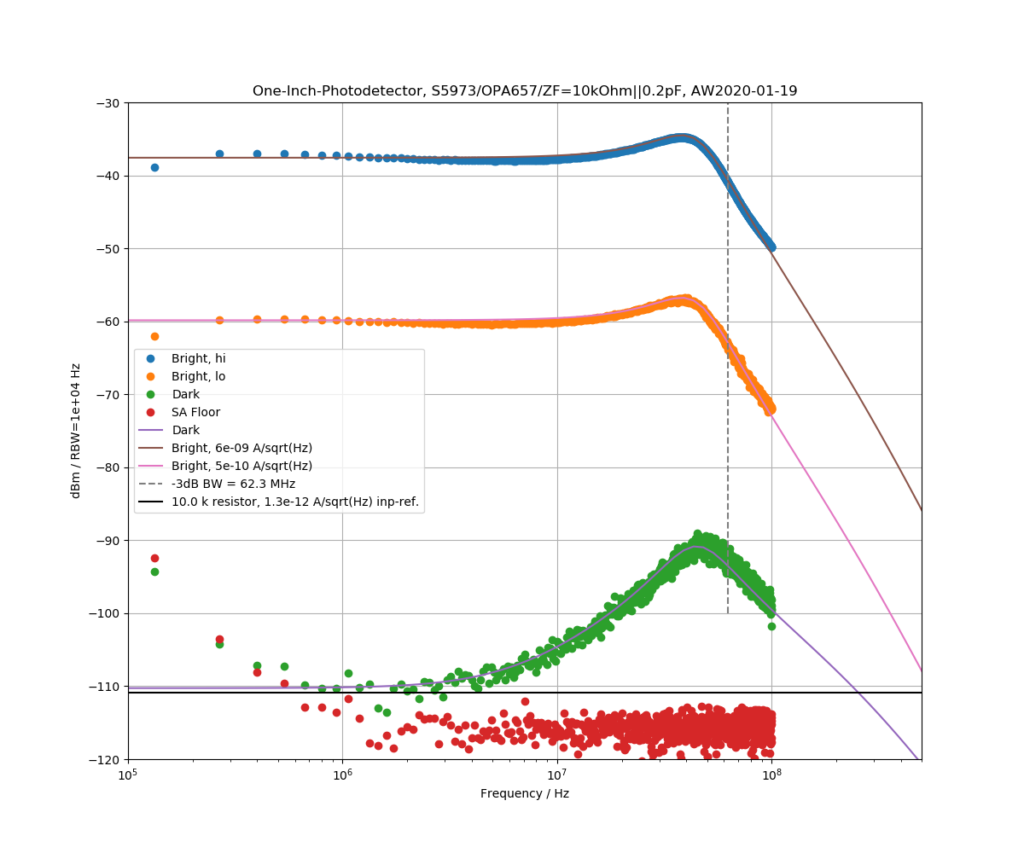
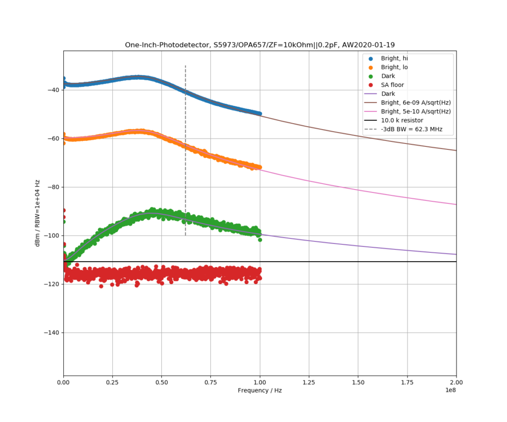
Ideally we'd want the dark-noise to be close to the thermal/Johnson noise of RF (like it, roughly, is at <10 MHz), but the circuit has a noise-peak as the -3dB bandwidth is approached. The 'bright' detector response was measured by shining light from a VCSEL onto the detector and modulating the laser with the TG output from the spectrum analyzer. Moving the divergent laser source closer or further away from the detector adjusts the signal level.
Here is the same plot with linear frequency scale.
Here's a transimpedance amplifier board that fits inside a 1" lens-mount. It has low noise LDOs (LT3042 and LT3094) and a SOT-23-6 op-amp footprint (for e.g. OPA657 or OPA847).
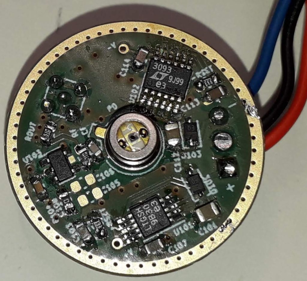
The first board has a S5973 photodiode, an OPA657, a 10 kOhm feedback resistor, and a 0.2pF feedback capacitor. The circuit self-oscillates without any feedback capacitor.
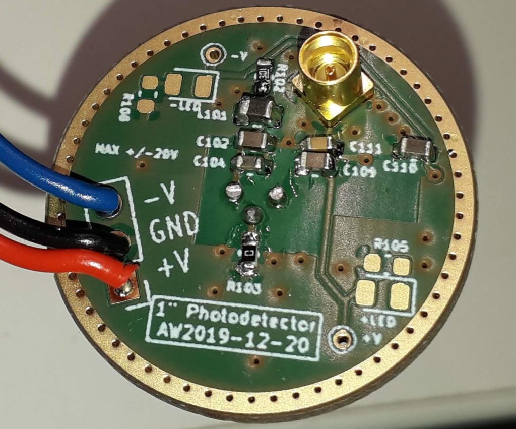
The backside of the board has an MMCX-connector for the output signal, and 3 wires for power supplies (max +/-20V).
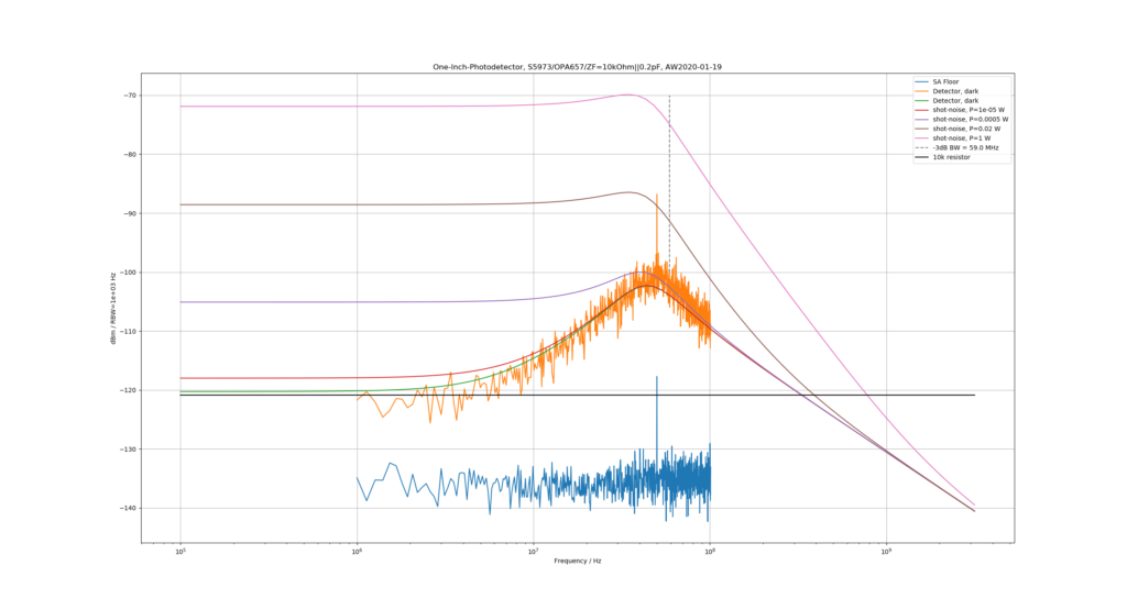
The noise-floor shows an ~18 dB bump as the 59 MHz -3dB bandwidth is approached - not that great. At low frequencies the noise-floor agrees with the thermal noise of a 10k resistor. Shot-noise from about 10uW optical power, producing a 4 uA photocurrent (photodiode responsivity ~0.4A/W), should be clearly (3 dB or so) above the 10k resistor thermal noise floor.
The noise-bump could be decreased with a larger feedback-capacitor, but this reduces bandwidth. The source capacitance is due to the S5973 photodiode (1.6 pF) and the differential (0.7 pF) and common-mode (4.5 pF) input-capacitance of the OPA657 op-amp. Clearly a lower input-capacitance opamp would be better. Stay tuned for tests with OPA858...
Note to self: can't use the Siglent SA's default detector mode of "Positive-peak" if we want quantitative dBm numbers from the analyzer. Use "sample" detector mode!
High-speed op-amps from TI, in a somewhat challenging WSON8-package...
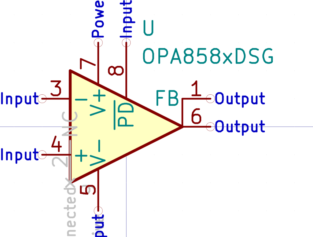
OPA858 is a 5.5 GHz GBWP FET-input amplifier (stable at gains >= 7V/V), and the OPA859 looks like a slower 1.8 GHz unity-gain stable version.
OPA855 is a 8 GHz bipolar input opamp, gain >=7V/V.
These should be useful where OPA847 and OPA659 were used previously, e.g. in high-speed transimpedance amplifiers.
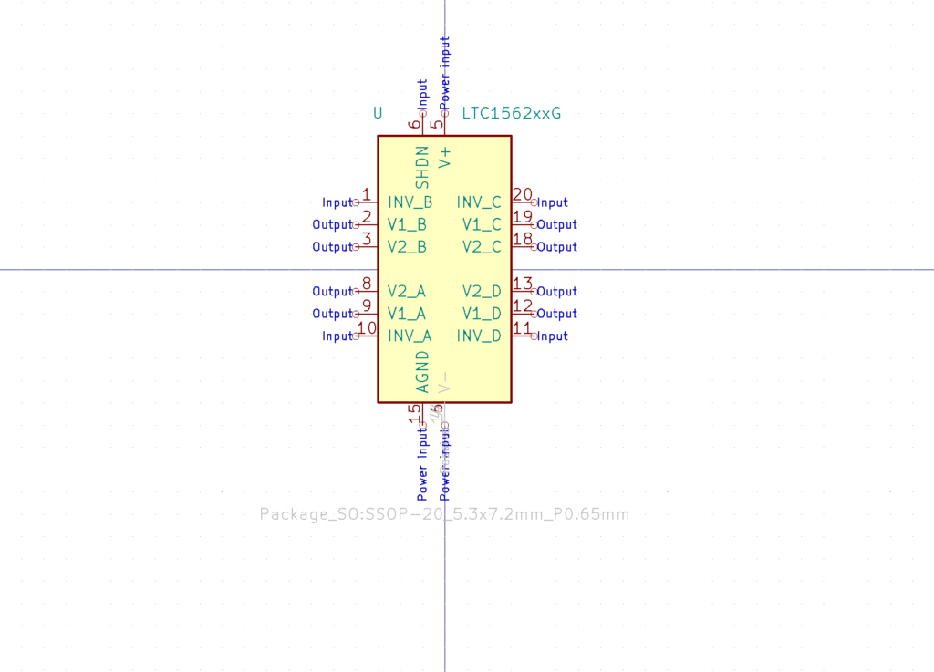
LTC1562 quad op-amp for building active filters at 10 kHz to 150 kHz.
