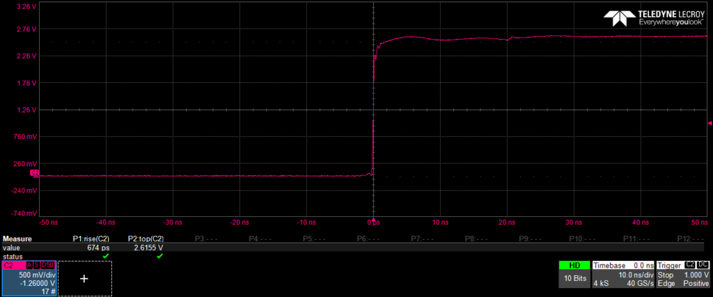
With a longish BNC-cable between a PDA-output and a 4 GHz oscilloscope we see a 10%-to-90% rise-time of <700 ps.
Recorded at 2x speed with OBS from the youtube live-stream, then converted to MP4 with VLC, then run twice through Garmin Virb Edit producing 8x speedup both times.
We've completed a second magnetic shielding layer, based on the same plywood+METGLAS concept as the first shield. This should further shield the 88Sr+ ion from unwanted magnetic field fluctuations. To further reduce the DC-field we've now applied a counter-field using a few milliAmps of current through three coils that surround the ion trap.
When the Zeeman components are this close together (the field is <0.4 uT) it is fairly quick to scan over the components. Here we see the four innermost pairs of peaks +/-C1 through +/-C4 of the clock-transition at 445 THz (674nm red light!). One scan runs in about one hour - and will be plotted on top of the older scans. We shoot 100 pulses of the laser-light at the ion and the height of the bar shows how many times we successfully drove the ion into the dark clock-state.
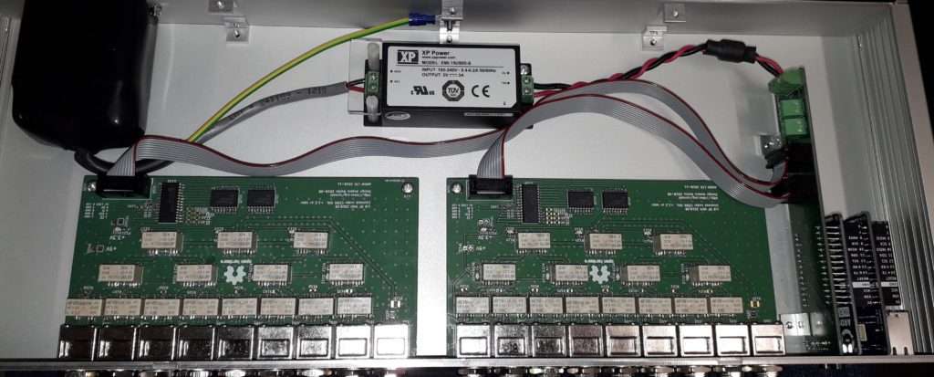
Slight design changes to the RF Multiplexer design.

Laser cut plywood test-project: a 2V geodesic sphere, diameter 200mm. Next is sanding the triangles a bit and then figuring out how to connect them neatly together.
(Built a few months ago, but better blog late than never..)
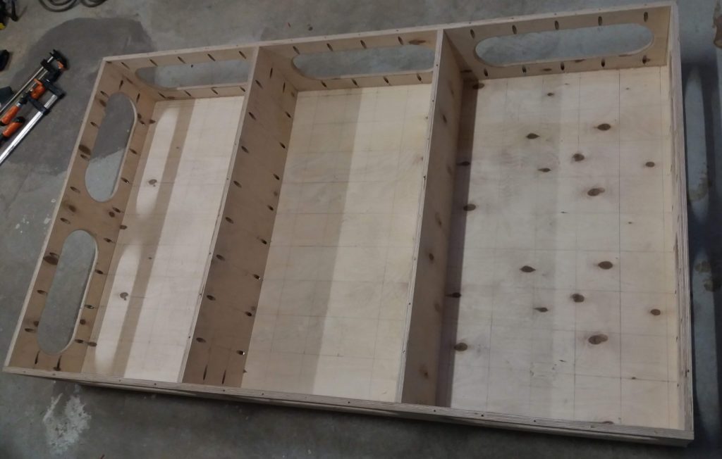
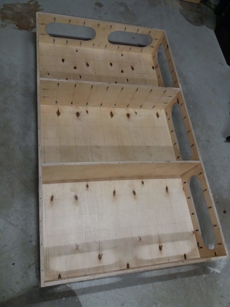
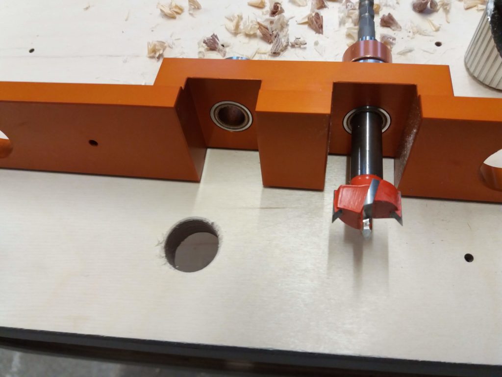
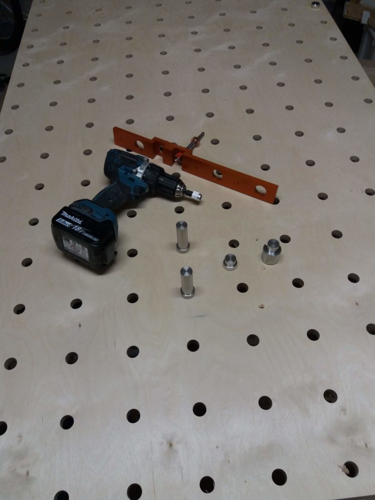
Here's a 1600mm-by-930 mm workbench built from two sheets (1220mm x 2440mm, 4-by-8 metric feet) of 15mm plywood. It's a torsion-box design with the top and bottom sheets separated by 240mm. The sides have rounded openings that create storage-bays for tools etc. The top has 20mm diameter holes drilled using the parfguide-system (it uses pythagoras 3-4-5 triangles to get the holes reasonably accurately positioned). The hole-grid is 10x17 so there are 170 holes in total. Assembled using pocket-hole screws.
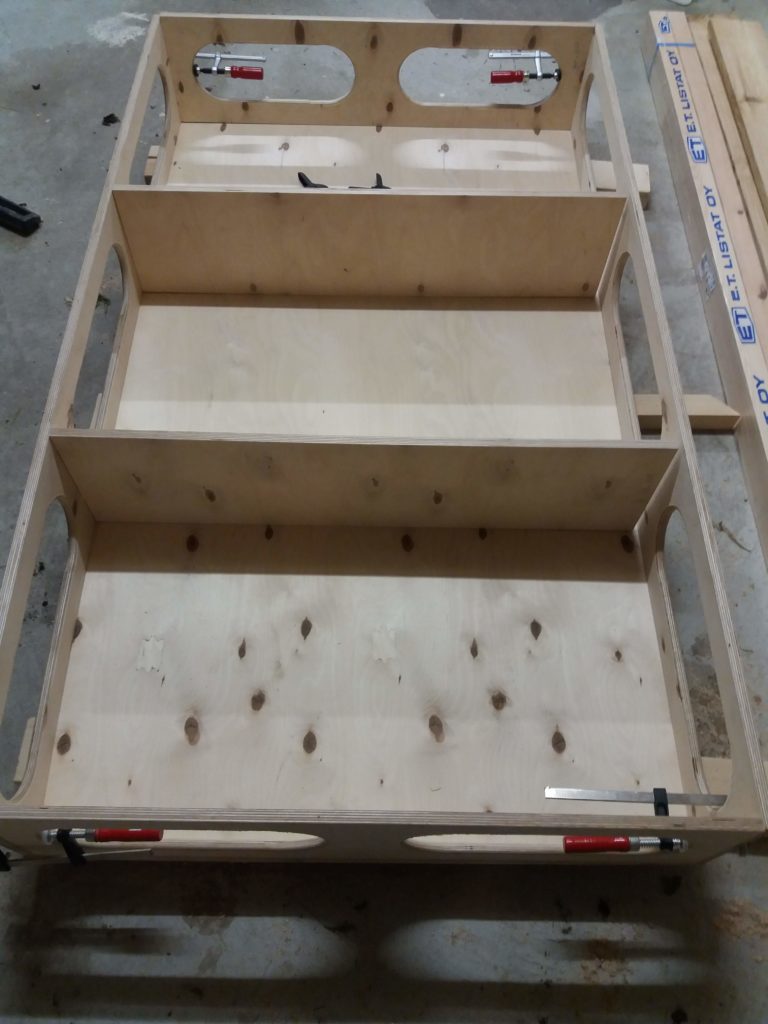
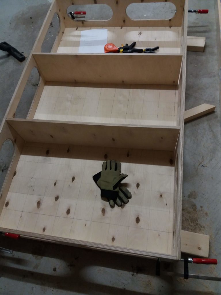
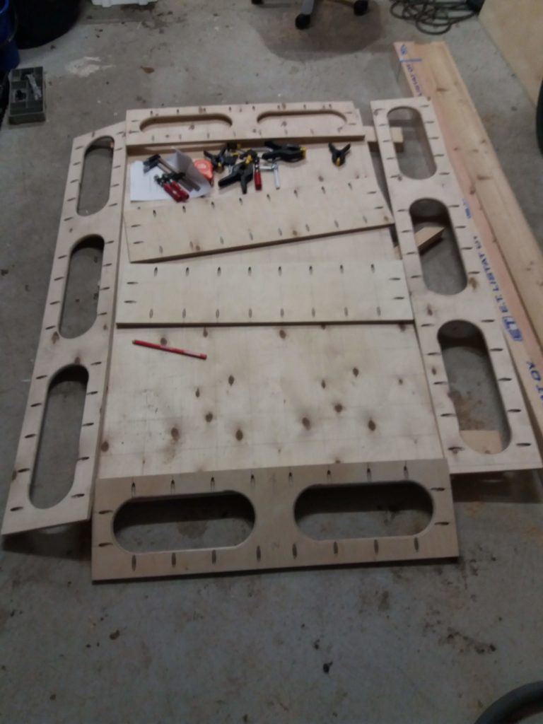
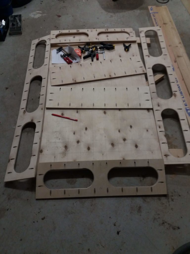
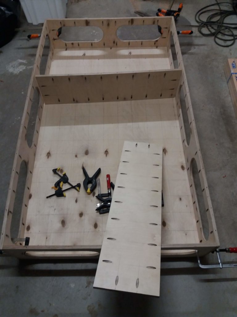
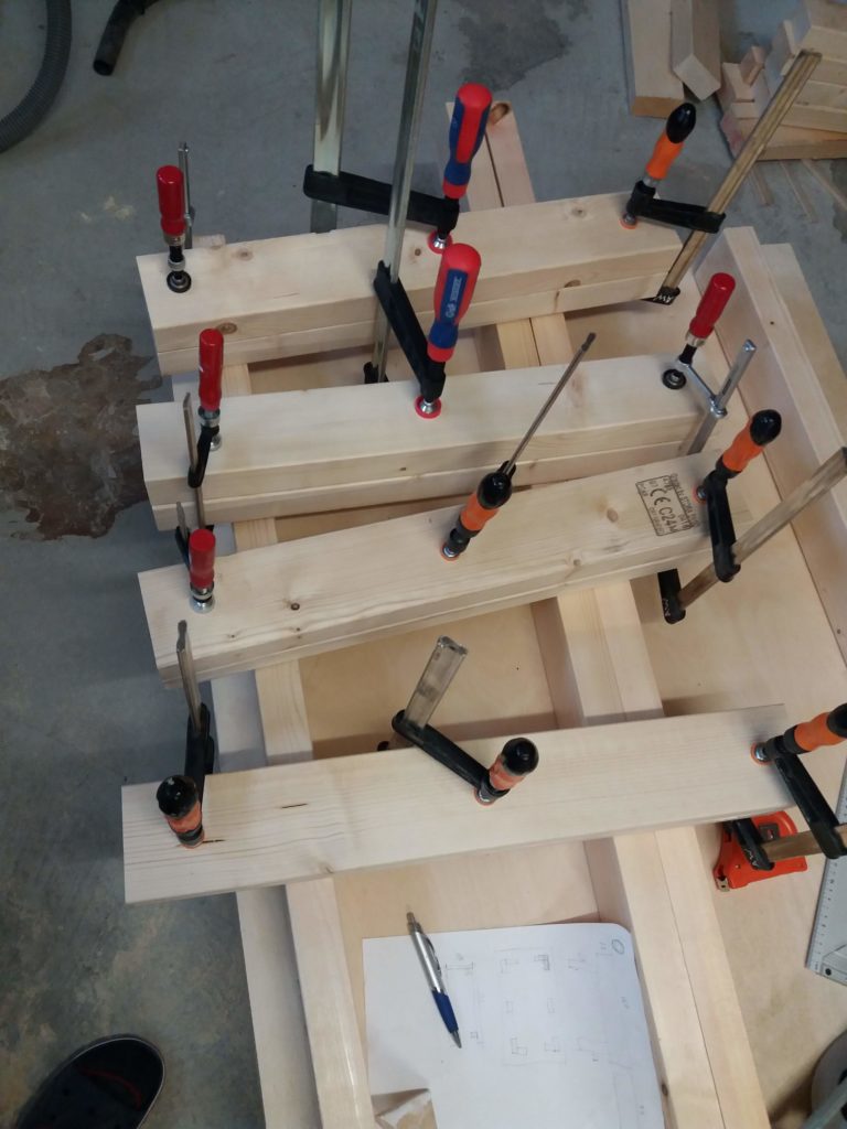
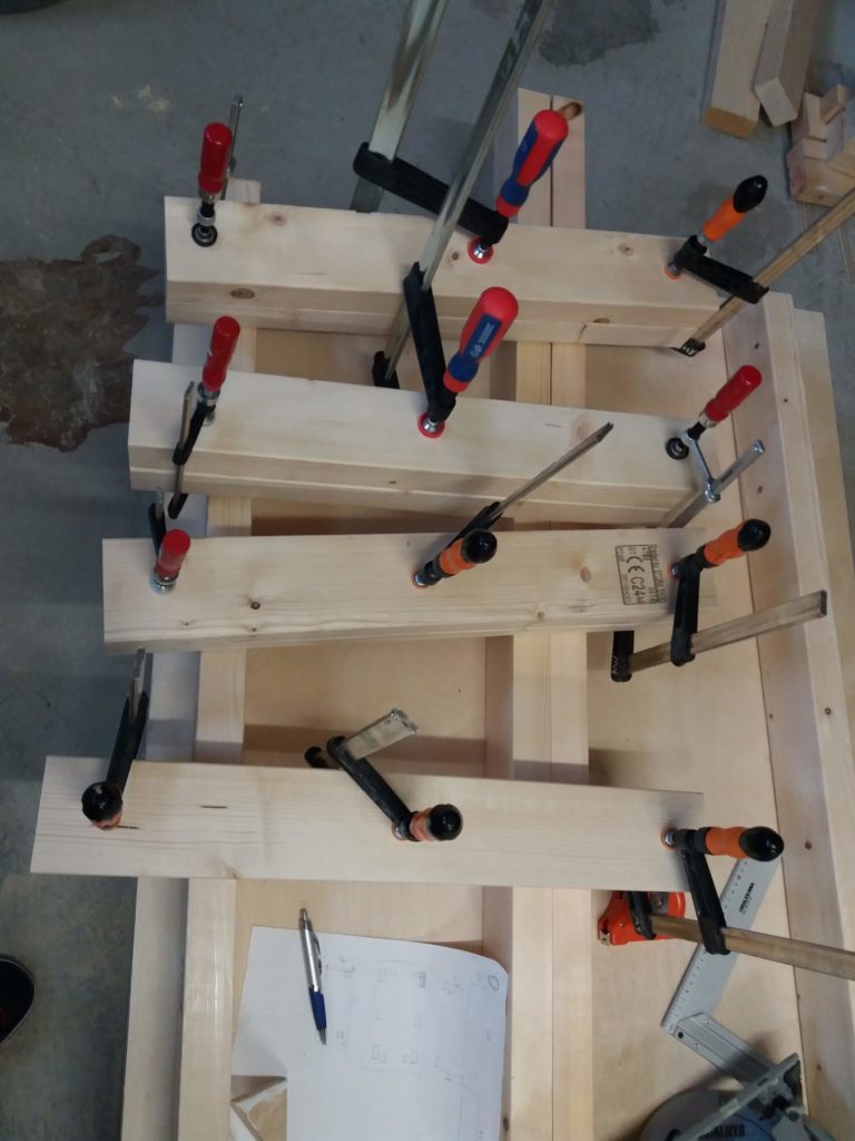
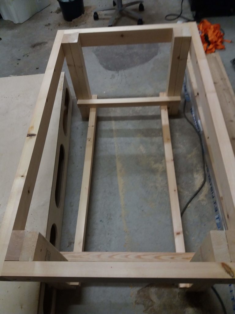
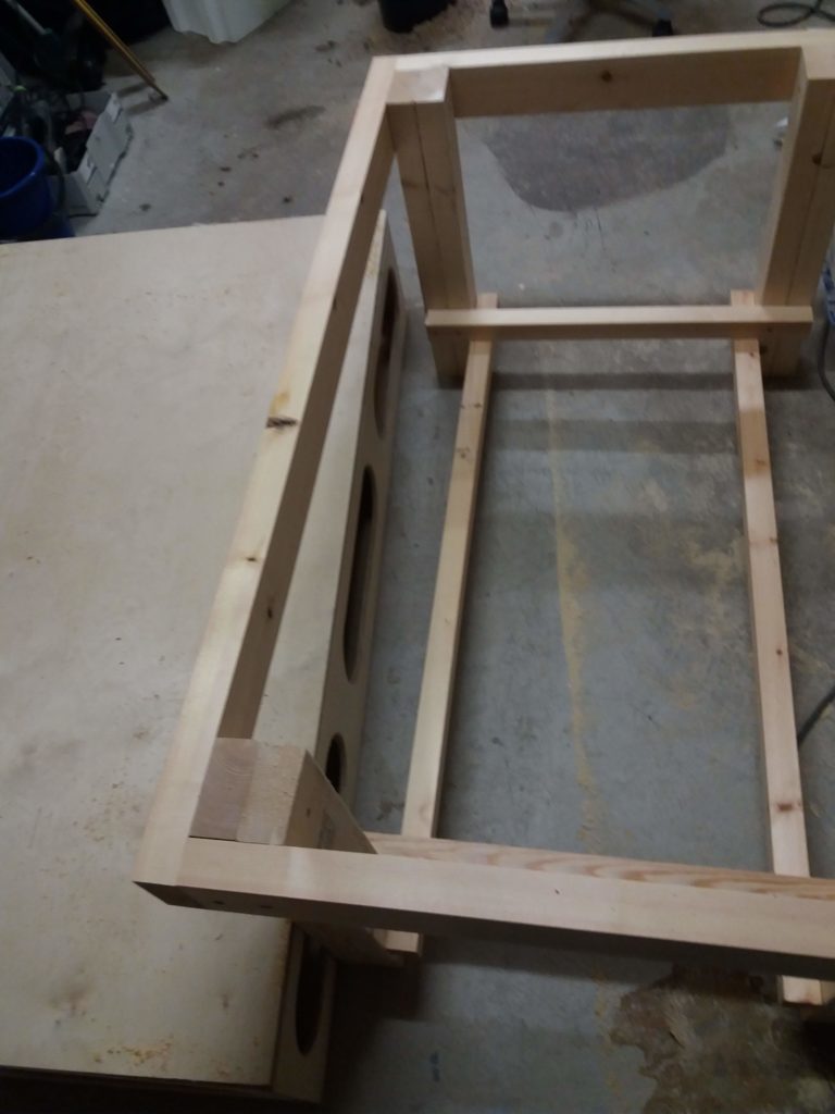
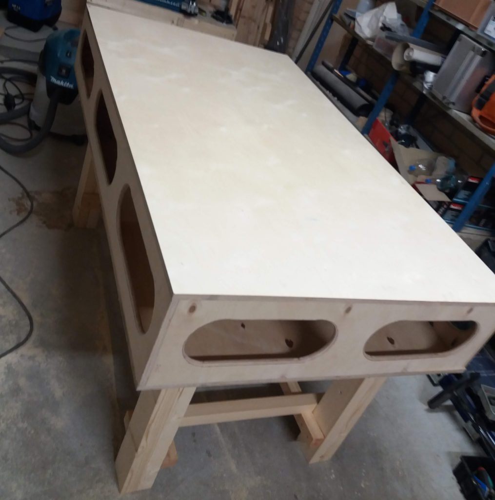
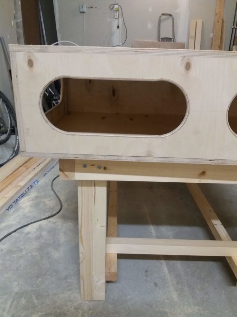
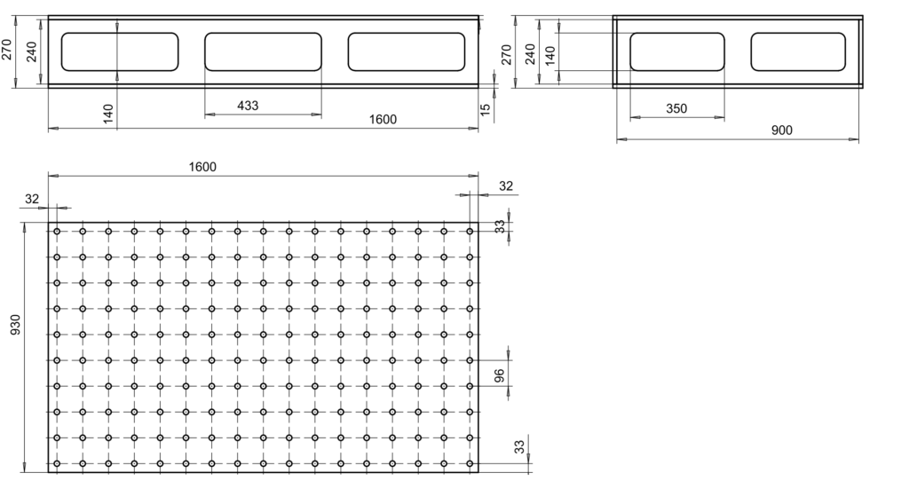
Here's a rough sketch of the dimensions. The dimensions were chosen to fit my workshop, so that it could be built from two 1220mm-by-2440mm sheets, and the dimensions rounded to fit the 96mm-by-96mm parfguide hole pattern nicely.
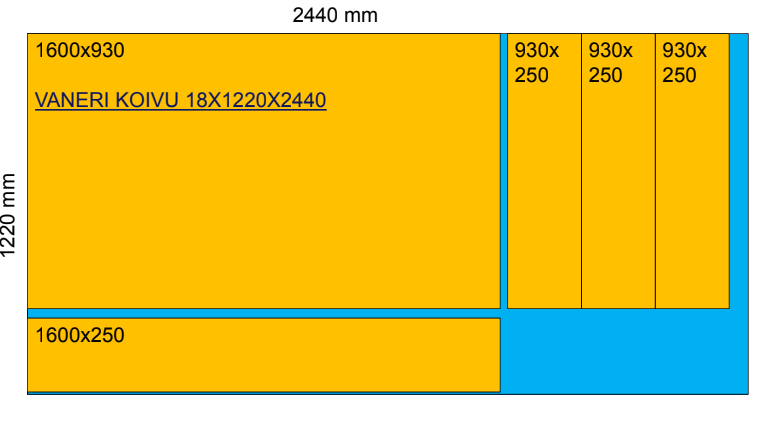
The pieces needed can be cut from two sheets of plywood, resulting in two top/bottom pieces, two long-sides, two short-sides, and four internal dividers. I only used two of the dividers.
There are a lot of torsion-box or "Paulk workbench" builds out there, here are some links:
Axminster sells this UJK mitre gauge fence, which replaces the stock mitre gauge/fence on my table-saw. The small coin-sized guide at the front needed a bit of filing to fit in the slot of the Makita.
First try at using the 50W CO2 laser cutter at the Iso Omena library. Material is 4mm Birch ply (K-rauta). I didn't have time to optimize the speed/power settings, so the edge-finish is quite burned, and a flame appears from time to time. There was a 3M tape-film (?model?) available, which when taped over the plywood-to-be-cut should reduce burning and flaming - but I didn't have time to try it.
Workflow: DXF files exported from CAD, the into Adobe Illustrator, set all linewidths to 0.01mm, then save as PDF, then print from Adobe Acrobat to the Epilog printer-driver, set speed/power for the material, send to the machine, set the (0,0) coordinate (top left) for the job, and press Go!
Here's the latest preliminary result from the VTT MIKES 88Sr+ ion clock (in case you missed the live-stream!):
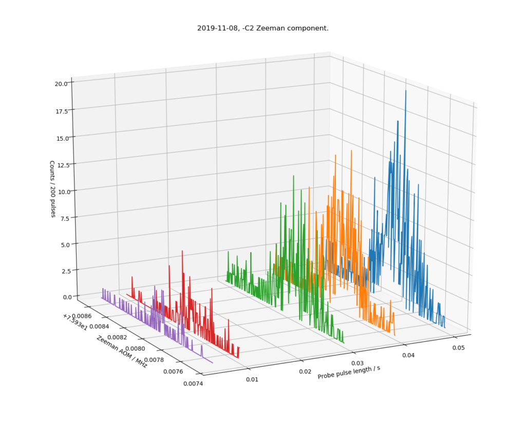
This shows a ~2 kHz slice (left axis, double the 1 kHz shown, because we plot the input frequency of a double-pass AOM) of the optical spectrum around 445 THz, where we expect to find the -C2 Zeeman component of the clock-transition in 88Sr+ (a secondary representation of the SI second). The right axis shows the probe-pulse length in seconds, where we see only a few percent excitation (z-axis) at short pulse lengths, but a clearer signal up to >10% at longer probe pulse lengths of 40 and 50 ms.
It ain't pretty, but considering the carrier is at 445 THz, this noisy and broad looking 800 Hz wide peak is still a measurement to a relative level of 2e-12. When fully operational a line-width of <10 Hz (2e-14) is expected.
Our experiment now has one metglas magnetic shield. This particular Zeeman component (-C2) has a sensitivity of 11 kHz/uT, so the observed linewidth of 800 Hz could be caused by a low-frequency AC magnetic field with an amplitude of 30-40 nT or so. We think the remaining DC-field is around 1.6 uT (down from 66 uT without the metglas shield).
Among other improvements, next is building a second metglas shield, to reduce AC fluctuations in the magnetic shield even further. Stay tuned...