skiing: petikko, 9km
Did two laps around the 4.7 km cross-country skiing track at petikko today. I should learn some better skating technique...

Links - 2011 Feb 27
- Discovery’s Final Launch Viewed from Airplane -
- Testissä Nokia E7 -
- ThinkPads, Astronauts, and Robots -
- Hand Brazing a Bicycle Frame -
- The Prints of MakerBot Artist-in-Residence Marius Watz -
- Simulation of the deflected cutting tool trajectory in complex surface milling -
- Robot Hummingbird Nano Flying Vehicle -
Force-clamp feedback for optical tweezers
A ~16 um long DNA-molecule is tethered between optically trapped plastic beads. Beads are held by a stationary trap (lower blue cross-hairs) and a steerable trap (upper green cross-hairs). The graphs on the right show the measured force (red) and the force set-point (blue) (top), the distance between the traps (middle), and the force-extension curve with a green cross indicating the current value (bottom). A force-extension curve of the tether is first obtained manually, before force-clamp feedback is switched on at t=24 s. The force set-point is first at 5.5 pN, then increased to 11.4 pN at 30 s and finally increased to 17.4 pN at 35 s. Scale-bar 5 µm. Anders Wallin et al. University of Helsinki, Finland, 2011.
Links - 2011 Feb 20
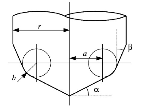
Cutter shapes
The four basic cutter shapes in opencamlib are CylCutter (cylindrical or flat-endmill), BallCutter (spherical), BullCutter (toroidal, filleted-endmill), and ConeCutter (cone, "v"-cutter).
With CompositeCutter it is then possible to combine these four into sensible combinations (such as the APT-tool). Below the combinations where the outer part of the cutter is conical, and the inner part is one of the four basic shapes. They are named CylConeCutter, BallConeCutter, BullConeCutter, and ConeConeCutter.
The general edge-push function for the cone shape isn't done yet, so there are no waterlines (except in special cases) for the cone-shape.
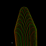
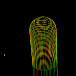
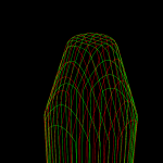
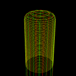
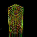
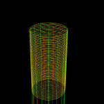
These inverse-tool-offset ("ITO") type images were drawn by using drop-cutter (red and green) and waterline (yellow) on a very narrow and tall triangle, so the toolpath shape looks like the inverted cutter.
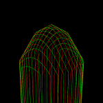
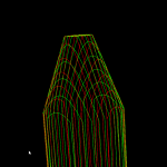
Waterline fix
In the general edge-push function there was a guard against horizontal edges, since they are supposed to be handled by a special horizontalEdgePush() function. But there was no check for vertical edges. They are special too, and caused the rather strange looking behavior with BallCutter seen below.
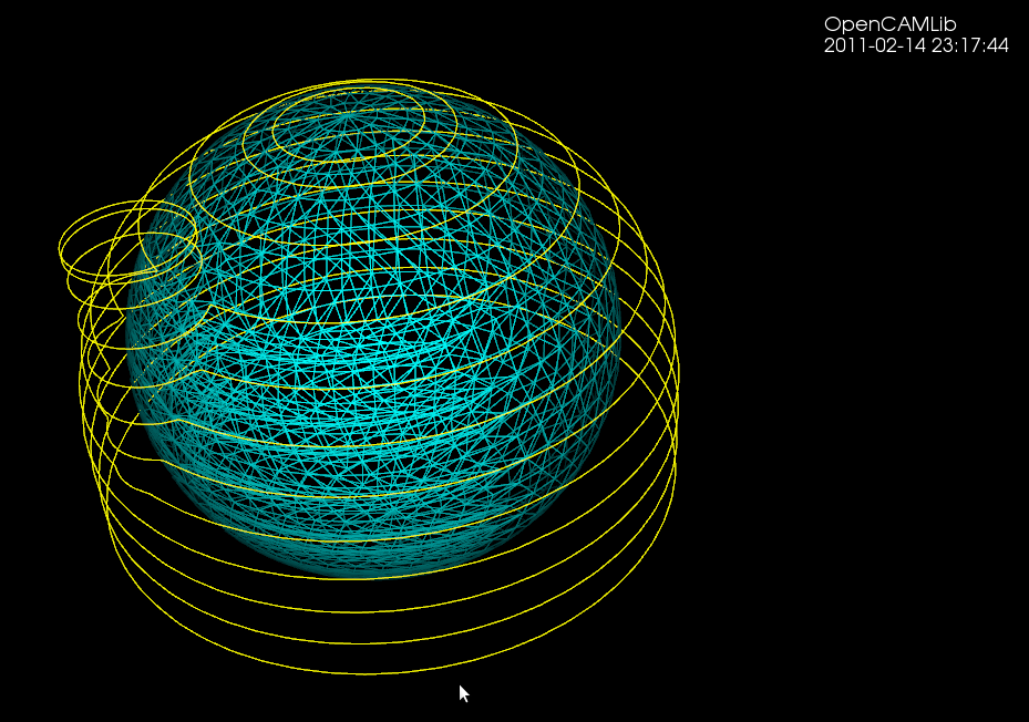
With BullCutter the code stopped at an assert() and there was no toolpath output at all.
This is now hopefully fixed and we simply give up and return in generalEdgePush() if we encounter a horizontal or a vertical edge. These should be handled upstream by simpler specialized functions. Never assume general position is the take home message I guess...
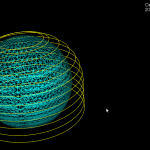
VD algorithm animation (zoomed out)
Some more youtube-art:
Links - 2011 Feb 13
- Garmin Edge 800 Review -
- PrimoGraf Drawing Machine -
- Carbon Fiber Like You’ve Never Seen Before -
- Canon’s New EOS 1100D Is Cheap But Capable -
- Canon Rebel T3i (EOS 600D) Preview -
- Canon Rebel T3i / EOS 600D announced and previewed -
- Canon Rebel T3 / EOS 1100D announced and previewed -
- Tiny $150 PC Fits in a Power-Plug -
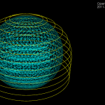
VD algorithm animation
Some notes on the Sugihara&Iri 1994 topology-based algorithm for incremental construction of the voronoi diagram for point sites.
(A) We start with initial VD for point sites that have already been inserted. We want to insert a new site, shown as a yellow sphere.
(B) We then find the VD face to which the new vertex belongs. Among the vertices that bound this face we search for a seed-vertex, shown in pink. This is the vertex that is closest to the new generator.
(C) From the seed vertex, we search for more vertices that should be deleted(red). The vertices should form a tree (a connected, acyclic graph). Vertices that are closer to the new site than to any other site should be deleted. However due to floating-point errors it's not possible to blindly rely on an inCircle() predicate for finding the delete-tree. It's necessary to also enforce the correct topology, namely (i) the delete-vertices should form a tree, and (ii) for any incident face, the delete-vertices are connected. This ensures that no old face of the graph is deleted or split in two.
(D) Identify the edges to be deleted (red), and edges on which we need to generate new vertices (green).
(E) Generate new vertices on the green edges, and connect all the new vertices by new edges. These new edges form a new face corresponding to the newly inserted site.
(F) Remove the red/delete-vertices and edges. We are left with what we want: the VD of all the old sites and the new site.

Another picture from the original 1994 paper. The new site is not shown, but by some process we have found the delete-tree (u1,u2,u3,u4) shown as solid dots. New vertices are then generated on the "in-out" edges (u2-u10, u2-u5, u3-u6, u3-u7, u4-u8, u4-u9), shown as unfilled dots. The unfilled dots are connected with new edges (dashed lines) that form the new facet (shaded area). Image borrowed from: Sugihara&Iri 1994.

Here is an animation of the algorithm at work when inserting about 100 random points: