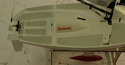
Timo brought along his latest toy, a Micro Magic, to our annual radiosailing winter meeting. This thing really is small compared to a Marblehead or an IOM! It's an all 'plastic-fantastic' ABS moulded boat, but you do have to glue the deck to the hull in this Racing version of the kit. The vitals are LOA=554 mm, Beam=178 mm, Weight=980 g, Height=980 mm.
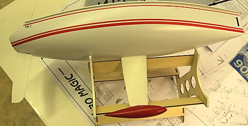
The fin and rudder are made of ABS plastic, and the bulb is lead. There are different sized bits that can be inserted fore and aft of the fin in the finbox to adjust the position of the fin for different conditions.
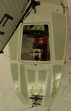
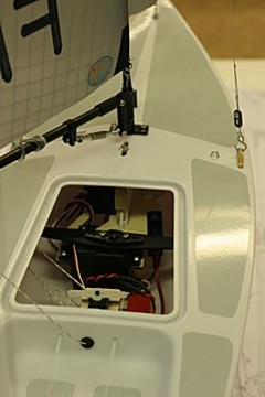
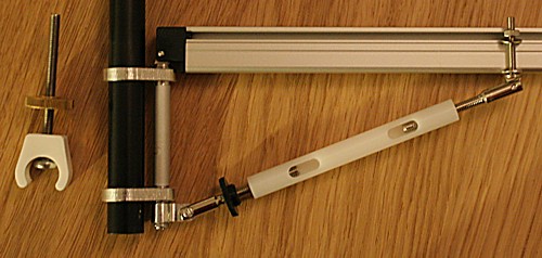
An arm-winch controls both sails, the mainsheet on the left side of the boat and the jibsheet on the right. Timo is using a micro-servo for the rudder, but I understand standard sized ones are used too.
There's one central hatch with a rubber seal, but I doubt it's watertight enough to be used without tape on top.
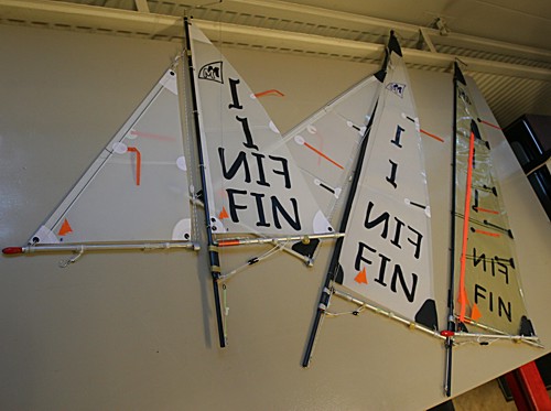
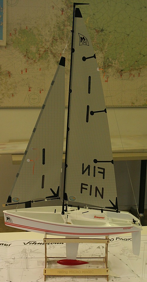
The standard carbon mast is 5 mm in diameter, and comes with two sidestays, but Timo has made some more rigs using 6/4 mm carbon tube and intends to use these rigs without sidestays. A bit surprisingly rule-writers around the world have usually not put an upper limit to the number of rigs, so I understand some skippers have made up to 5 or 6 different rigs! (the smaller ones all fit within the biggest one)
In terms of number of boats/skippers the Micro Magic is a definite success with ca 1000 or more boats registered in both Germany and the Netherlands. It makes you think that the traditional international radio sailing classes (IOM, M, 10R, A) have somehow failed since they have not as far as I know attained similar popularity. Marketing wisdom tells us that this must be because of the five Ps: Product, Place, Price, Packaging, Promotion. (I'm leaving 'Product' last in my ramblings below, since I have the most doubts about this P)
Price: the Micro Magic wins hands down over an IOM or any other international radio sailing class. The whole MicroMagic kit with the tall rig, a basic two channel radio, and everything you need to go sailing costs about the same (300 EUR) as three suits of sails for an IOM. By comparison, I estimate a competitive IOM with three rigs and radio from a commercial builder costs about 2000 EUR. Home building a boat to the same standard and performance is not much cheaper.
So does price really matter? Die-hard radio sailors usually say no: travelling to events, staying in hotels, spending all that leisure time racing etc. constitutes a much bigger investment than the price of the boat. For someone who travels internationally every year and to all big events nationally it probably doesn't matter if the boat costs 500 eur, 1000 eur or 2000 eur. But for the beginner it does matter! I see very few newcomers to competitive IOM racing in Finland - maybe that's because of the high price tag? To really get into the class you need a competitive, watertight, and fully functional secondhand, or almost completely built new boat, and that's going to cost you about 2000 eur...
Place: go to the local hobby store, hand them your credit card, and within 1-2 days you will be on the water sailing this boat. Depending on your country, getting an IOM is either a lot harder or just a bit harder. There are no industrial builders (The Robbe Windstar is not really a competitive IOM), so you can't buy an IOM from a hobby store, and the salesperson in the shop is not likely to even know there exists such a thing as an IOM class. All manufacturers are small, most amateur hobbyists and a handful of professionals, and usually sell boats in kit-form to keep down the cost. In countries where there are no commercial builders the situation is even worse. The seasoned radio-sailors do know the international suppliers, some personally, but a newcomer is quite unlikely to send a big amount of money to an unknown builder in a foreign country (and wait the usual 4-12 weeks delivery time).
Packaging/Promotion: Probably about equal between an IOM and a MicroMagic. Promotion will largely depend on what class your local club sails I guess.
Product: Here's where my doubts are. When moving from a Marblehead (4-5 kg weight, 1.3 m length) down to an IOM, the boat felt very nervous, unstable, and hard to sail in the beginning. An IOM is also definitely harder to trim for neutral balance. This was a move down in length from 1.3 m to 1 m, and in weight from about 4.5-5 kg to 4 kg. I haven't sailed a MicroMagic yet, but we must be talking about a completely different behaviour at 55 cm overall length and < 1 kg displacement.
On the other hand, do skippers want a boat that sails and handles gracefully, like a full-scale boat, or are most skippers just looking for a level playing field where they can have fun racing the boats? If the latter is most important, then there must be a bright future for boats like the MicroMagic. In reality very few people have time to design and build their own boat, so I don't think this argument against industrially produced boats really holds.
All of this seems to indicate smaller and industrially produced is better. But there must also be some kind of scale effect: If I show my IOM to someone on the street I'm sure most people would recognize it as more than a toy, capable of racing in widely varying conditions etc. Show the same people a MicroMagic and they will definitely think 'toy'.
This is an interesting topic, so I'd love to hear some thougs from my readers:
- I clearly haven't done my homework well enough, so could someone fill me in on the numbers of boats in the big countries for the various 'industrially' made classes: MicroMagic, RC-Laser, Victoria, etc.
- How does the MicroMagic sail in different conditions? preferably from people who have a solid background in Marblehead or IOM racing! How does it compare to an RC-Laser?
- If you have some deep thoughts on how to make a radio sailing class really succeed I'm also interested.