Inspired by this post on the pycam forum and by this 1993 paper by Luiz Henrique de Figueiredo (or try another version) I did some work with adaptive sampling and drop-cutter today.
The point based CAM approach in drop-cutter, or axial tool-projection, or z-projection machining (whatever you want to call it) is really quite similar to sampling an unknown function. You specify some (x,y) position which you input to the drop-cutter-oracle, which will come back to you with the correct z-coordinate. The tool placed at this (x,y,z) will touch but not gouge the model. Now if we do this at a uniform (x,y) sampling rate we of course face the the usual sampling issues. It's absolutely necessary to sample the signal at a high enough sample-rate not to miss any small details. After that, you can go back and look at all pairs of consecutive points, say (start_cl, stop_cl). You then compute a mid_cl which in the xy-plane lies at the mid-point between start_cl and stop_cl and, call drop-cutter on this new point, and use some "flatness"/collinearity criterion for deciding if mid_cl should be included in the toolpath or not (deFigueiredo lists a few). Now recursively run the same test for (start_cl, mid_cl) and (mid_cl, stop_cl). If there are features in the signal (like 90-degree bends) which will never make the flatness predicate true you have to stop the subdivision/recursion at some maximum sample rate.
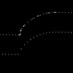
Here the lower point-sequence (toolpath) is uniformly sampled every 0.08 units (this might also be called the step-forward, as opposed to the step-over, in machining lingo). The upper curve (offset for clarity) is the new adaptively sampled toolpath. It has the same minimum step-forward of 0.08 (as seen in the flat areas), but new points are inserted whenever the normalized dot-product between mid_cl-start_cl and stop_cl-mid_cl is below some threshold. That should be roughly the same as saying that the toolpath is subdivided whenever there is enough of a bend in it.
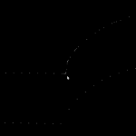
The lower figure shows a zoomed view which shows how the algorithm inserts points densely into sharp corners, until the minimum step-forward (here quite arbitrarily set to 0.0008) is reached.
If the minimum step-forward is set low enough (say 1e-5), and the post-processor rounds off to three decimals of precision when producing g-code, then this adaptive sampling could give the illusion of "perfect" or "correct" drop-cutter toolpaths even at vertical walls.
The script for drawing these pics is: http://code.google.com/p/opencamlib/source/browse/trunk/scripts/pathdropcutter_test_2.py
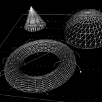
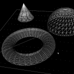
Here is a bigger example where, to exaggerate the issue, the initial sample-rate is very low:


Hi Anders,
that´s funny. I started the post in the PyCam forum and I linked to your website, because I thought you already implemented something like that by using Octrees. So your solution was started by the wrong assumption that you had solved this problem. 😀
Sometimes the internet has strange ways.
Years ago I was very much into model building and a build a IOM Vanquish. Then I bought a CNC mill to help my modelbuilding. Since then I had no time to build any more, cause I´m just trying to get the mill working. 😀
Anyway, don´t worry that nobody is interested in your blog. I read it regular and appreciate is a lot. Very interesting.
CU Michael
PyCAM now has something similar:
http://fab.senselab.org/en/node/174
Thanks for your helpful comment over there at my blog!
Just one question regarding your code: is it possible, that a deep recursion could trigger one of the assertions in line 67 at a rough edge of the model (due to float/double inaccuracies)? Or did I overlook the break condition?
Anyway: thanks for your blog post!
I've just posted a figure which shows how closely doubles/floats are spaced:
http://www.anderswallin.net/2010/11/on-the-density-of-doubles-and-floats/
if the minimum sampling is set well above this limit then I think the code should run fine.
I would welcome a bug report if anyone can make the assertions fail with realistic machining input parameters 🙂
Thanks for the clarification!
After taking another look at your code, I finally noticed the
condition, which should safely prevent the assertions from being triggered.
As you already mentioned in your blog post, the "min_sampling" limitation is currently static and thus maybe not suitable under all conditions. E.g. using a model with imperial units (inch) and a cutter diameter of 0.5mm would currently (min_sampling=0.01) lead to a minimum sampling distance of half the cutter's diameter.
Maybe you could use the current cutter size as a base for calculating the "min_sampling" limit? Something like 1/100 of the cutter's diameter would surely be sufficient for most applications.
Anyway: your implementation looks really nice and elegant!
You can use this to set the sampling value in ocl
For adaptive operations there is additionally
which you can use to set the minimum sampling interval.
I'm not sure which is better, guessing some reasonable defaults (probably good for the novice user), or not setting them at all and erroring out if setSampling() and/or setMinSampling() have not been called (probably better for the advanced user).
As you mention you could also do this when Operation.setCutter() is called and set the sampling and and minimum sampling based on cutter.getDiameter(). I think this isn't exactly great style-wise as the library user can hardly guess that the setCutter() method will internally/secretly call setSampling() and setMinSampling() behind the scenes.
You are right: from the perspective of a library the separate "setMinSampling" approach is propably the best.
Thanks for pointing this out!