I've made some more progress with my voronoi diagram code. I described the topology-oriented incremental algorithm earlier here (point sites) and here (line segments). When we want to add a new site (a point or a line-segment) to the diagram we should find a tree of to-be-deleted vertices/edges (red), create new (green) vertices on all in-out edges, and hook up the new vertices with new edges (green) to form the face for the new site. For point sites it looks like this(click thumbnail to see GIF animation!):
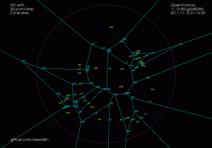
For line-segment sites we need to modify the in_circle() predicate to calculate the minimum distance from a point to a line-segment. Then we need a much more involved solver that figures out points that are equidistant from points/lines. There are four different cases: point/point/point, point/point/line, point/line/line, and line/line/line (or you could identify a fifth and sixth type of vertex if you treat the case where one vertex is a line-segment endpoint differently, see drawing here).
In addition to simple line-edges between two point-sites we now also get two new types of edges: between line/line sites we have line-edges (but parametrized a little differently), and between point/line sites we have parabolic edges. The basic algorithm however looks pretty similar: we again find the delete-tree (red), create new vertices (green), and hook them up with new edges (green) to form a new face. (again click thumbnail to see GIF animation!).
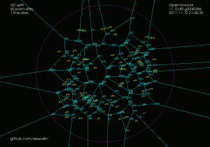
There are (at least!) two more complications arising with line-sites that don't show up with just point-sites. These are handled with additional APEX and SPLIT vertices, which don't really add new geometry or topology to the diagram, they just make the algorithm handle certain special cases correctly.
It turns out that with parabolic edges there can be cases where both endpoints of the edge are marked IN (red, or to-be-deleted), but some parts of the edge still needs to be preserved. To handle this case correctly we insert a new type of APEX vertex at the apex of each parabolic edge. These APEX vertices can be seen at the tip of each parabola in the GIF-animation above.
The second special case is more subtle. There can be situations where the algorithm finds a to-be-deleted set of vertices that contains a loop/cycle. This is obviously forbidden because that would delete a face from the graph - which isn't allowed. That's why we require the delete-set to be a tree. Here is an image:
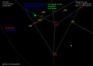
We are inserting a new line-segment (yellow) starting at 48. The IN-vertices already found are colored red. Vertex 142 should be marked IN because it is closer to the new line-segment than to any other site. However that would create a loop of red vertices (134-135-143-148-142-138) and the face corresponding to the point-site 133 would be deleted. The problem is similar to that with APEX points: the end-points of edge 148-142 are both marked IN, but the edge should not be deleted completely. To handle this case we need to insert a SPLIT vertex at a position on the 148-142 edge which will be preserved(i.e. marked OUT). We do this by projecting the site 133 onto the edge 148-142 using the line-segment(yellow) as a mirror. This vertex will be marked OUT and ensures that the 148-142 edge is not completely removed. The same reasoning should work for circular arc-sites where we project radially through the center of the arc.
Here is a longer animation (best watched at 1080p/fullscreen!) which shows the insertion of 100 point-sites followed (after around 1:15) by insertion of (non-crossing!) line-segments:
The code now runs without errors until about 50 line-segments. There are problems with finding the proper end-points for separators in degenerate cases where the solver positions vertices on top of each other or very very close to each other.
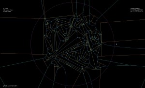
Update: Some further bugfixes and filtering solution-points by both maximum and minimum t-value (clearance disk radius) has made the code run without assert()'s or problems up to N=100 line-segments:
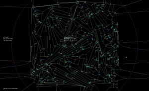
Update2: now up to 200 line-sites:
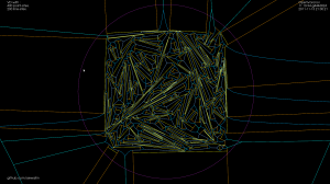
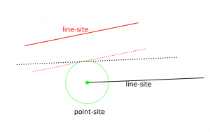
Update3: Here is one case which I have identified as "hard" for the vd-vertex location solver code. We have as input to the solver a line-segment, one of its endpoints, and a third site (in this case also a line-segment). In some cases it happens that the offsets (dashed lines) of these three input sites are nearly parallel, which results in bad numerical precision, and the resulting solution can have an error which is as much as 1e9 times the normal errors I see.
