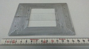
Update: here is the plate. Let's hope it is accurate enough (it is not face-milled on the underside...)

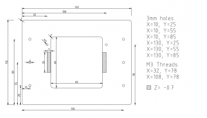
A plate for holding 76 mm x 26 mm glass slides in the microscope. My first ever 'real' drawing with LibreCAD (that website has been down for two days now, so try also librecad on sourceforge).

Drawing in PDF: chamber_holder
Drawing in DXF: plate_v2.dxf
You should also draw side view. Who ever is going to make this needs to know plate thickness, are the 3mm holes
through or blind holes, are M3 threads through or how deep thread you want if they are blind threads.
All those things can be shown at side drawing, or you must specify those things to this top view. Also tolerances would be important. I think you can use general tolerance, like +/- 0.1 mm, for hole places and for 140*110 mm outside dimensions, but maybe
26mm*5mm slots and 66mm*66mm square have more critical dimensions?
How those square corner 26m*5mm slots are going to be made?
Sorry about critic, but I just thought to express machinist point of view. I'm sure those things are very clear to you as a designer, but manufacturer doesn't have a clue!
Yeah the drawing is for in-house use. If I would out-source the job a better drawing would be required. I'm either making this myself on the WF-20 mill or the in-house workshop downstairs will make it on the new Dugard.
The internal corners don't need to be sharp, as long as the 76x26mm slide is held securely in place.
LibreCAD is only for 2D, so the different views would have to be drawn as separate drawings. If I need front/side/top views of a part it needs to be drawn in 3D and the CAD-program should extract the 2D drawings from that.
Yes, there's much more flexibility with in- house production. Please post a picture about this part when it's done.
LibreCAD and similar free 2D CAD softwares are very similar what expensive "State of art" AutoCAD use to be around year 2000-2004. Current 3D parametric CAD softwares are pretty big step ahead.