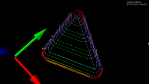
Update: Here is another example with the CL-points coloured differently. At each z-height the innermost loop is with the ball-cutter, next is the bullcutter, and the outermost loop is calculated for a cylindrical cutter. The points are coloured based on which test (vertex, facet, edge) produced them. Vertex-test points are red. Facet-test points are green. The edge-test is further subdivided into (1) a test for horizontal edges (orange), (2) a test for contact with the cylindrical shaft of the cutter (magenta), and (3) the general edge-push function (light blue for ball/bull, pink for cyl). If/when I get the cone-cutter done the cutter-location algorithms in opencamlib should be complete (at least for the moment...), and I can move on to more interesting high-level algorithms.
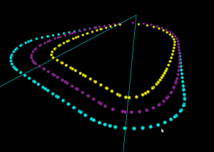
This figure shows one of the first times I got the push-cutter/waterline algorithm working for bullcutter (filleted endmill, bull-nose cutter, toroidal cutter, a dear child has many names...).
The thin cyan lines are edges of a triangle. The outer cyan spheres are valid cutter locations (CL-points) for a cylindrical endmill. The innermost yellow CL-points are for a spherical (or ball-nose) endmill. Between these two point-sets the new development is the magenta points, which are CL-points for a bull-nose cutter.
The algorithm works by pushing the cutter at a specified Z-height along either the X-axis or the Y-axis into contact with the triangle. There are three sub-functions for handling the case where the cutter makes contact with a vertex, the triangle facet, and an edge. The edge-contact case is the non-trivial (read "hard") one. The approach I am using is based on the offset-ellipse, courtesy of the freesteel blog. Pushing a toroid into contact with an edge/line is equivalent to pushing the cylindrical "core" of the bullcutter into contact with an edge that has been 'inflated' to a cylinder with a radius equal to the bullcutter corner radius. Slicing this cylinder/tube with a z-plane gives us an ellipse, and the sought cutter-location lies on the offset of this ellipse. I should make some diagrams and post longer/better explanation later (I wonder if anyone reads these 🙂 ).
The bullcutter is important not only in itself, but also because it is the offset of a cylindrical cutter. When we want to do z-terrace roughing with a cylindrical cutter, and specify a stock-to-leave value, we do it by calculating the toolpath with cylcutter->offsetCutter() which is a bullcutter, and then actually machining with the cylindrical cutter. That will achieve the desired stock to leave (to be removed later by a finish operation).


I read your posts 🙂 I'm still not completely sure what you are trying to do. Write some CAM software? Write a machining simulator to show what the part should look like before it's cut?
There is clearly a lack of open-source CAD/CAM applications. Something like solidworks or mastercam is not a program you sit down and write over a weekend. If opencamlib can at least provide algorithms for toolpath generation and verification/simulation, then we would be one step closer to a working open-source CAD/CAM solution.
Hi Anders,
thanks a lot for your inspiring posts! I am one of the developers of PyCAM (a toolpath generating software) and I consider your blog to be a great source of ideas for my developments.
Hopefully I will manage somewhen to switch the calculation backend of PyCAM to opencamlib - it will surely be worth the effort.
Keep on the good work!
Lars
Hi Lars,
Thanks for your message. I have just tried PyCAM 0.4.1 and it looks nice and simple. I am missing some low-level controls for the sampling-tolerance in both drop-cutter and waterline/contour.
We should set up a standard benchmark case so that different algorithms and improvements in speed can be tested.
Where are the pycam crowd/developers hanging out?
This list looks pretty empty: http://sourceforge.net/mailarchive/forum.php?forum_name=pycam-devel
Anders
Hi Anders,
I am missing some low-level controls for the sampling-tolerance in both drop-cutter and waterline/contour.
I am quite new to the world of machining - thus I don't know all the words, yet 🙂
So: what do you mean with "sampling tolerance"? The distance between adjacent lines? The distance between the points in a line? The remaining material?
We should set up a standard benchmark case so that different algorithms and improvements in speed can be tested.
That would be nice, indeed. But the variety of parameters will make it hard to compare the results, or?
Do you have an idea, which kind of model would be suitable? Currently I try to concentrate on organically shaped models instead of geometrically defined objects.
(hopefully you can follow my broken English)
Where are the pycam crowd/developers hanging out? This list looks pretty empty: http://sourceforge.net/mailarchive/forum.php?forum_name=pycam-devel
yes - sadly!
Basically we are right now four people - two people with the intention to contribute and two people who actually did something already 🙂
The other one besides me is the initiator of the project. But he admitted, that he will not be able to put time into this project this year. So basically I am more or less the only active deloper right now ...
From time to time I post some development news at the pycam developer blog:
PyCAM developer's blog
Regarding the possible use of opencamlib for PyCAM: the main problem for me right now is, that I am quite new to the world of distributing libraries/binaries. I am more focussed on developing with script languages (Python/Perl). Thus I am currently not sure how (technically) I could distribute opencamlib along with PyCAM. Do you have any experience with mixing (and distributing) these two worlds?
Lars
PS: a preview button would be nice to check the formatting of a comment before posting it 🙂
I have just installed the ajax comment preview plugin from here: http://wordpress.org/extend/plugins/ajax-comment-preview/
test. bold smile: 🙄