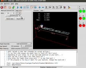
By popular demand a simple example of how to modify the stepper_mm sample configuration to output phase-A/phase-B quadrature signals (stepgen type=2).
In core_stepper.hal we specify step type 2, and re-name/wire the stepgen output:
loadrt stepgen step_type=2,2,2
net XA <= stepgen.0.phase-A net XB <= stepgen.0.phase-B net YA <= stepgen.1.phase-A net YB <= stepgen.1.phase-B net ZA <= stepgen.2.phase-A net ZB <= stepgen.2.phase-B
Then in standard_pinout.hal we wire the phases to the parport:
net XA => parport.0.pin-03-out

net XB  => parport.0.pin-02-out

net YA => parport.0.pin-05-out

net YB  => parport.0.pin-04-out

net ZA => parport.0.pin-07-out

net ZB  => parport.0.pin-06-out
Since I have neither a parport nor an oscilloscope at hand right now I'm using some pyvcp LEDs to look at the A/B signals. These are set up with two changes to the INI-file:
[DISPLAY]

PYVCP = phaseleds.xml
and
[HAL]

POSTGUI_HALFILE = pyvcp_phaseleds.hal
The files I'm using are here: phaseleds.tar
Now it is possible to look at the blinking of the LEDs when the machine moves and see the 90-degree out-of-phase square waveform (see also image here).

Awesome! This is the sauce I was looking for. I have a MAXNC-10cl that I was finally able to get moving because of this sample code. I still have a lot of tuning to undertake before it's ready. Thanks!