Author: admin
VTK test
Tried to make the code from last time a bit clearer by splitting it into two files:
vtkscreen.py and test2.py
conversion to video again by first converting PNG to JPEG:
mogrify -format jpg -quality 97 *.png
And then encoding JPEGs into a movie:
mencoder mf://*.jpg -mf fps=25:type=jpg -ovc lavc -lavcopts vcodec=mpeg4 -ac copy -o output.avi -ffourcc DX50
Building Bow Bumpers
Most model-yacht classes require a soft bow-bumper to be installed on the bow of the boat, to prevent serious damage when the inevitable collisions happen.
We milled a bow-bumper mould for the PIKANTO a while back. A first test was made using the normal Frekote+wax release agent (which we use when moulding boats with epoxy+glassfiber) in this mould and a standard bathroom silicone. Not very successful. The silicone stuck to the mould, cured slowly, etc.
Googling for this a bit it seems there are separate release agents made for silicone-casting. The simplest solution I found was to use Vaseline (a.k.a. petroleum jelly). This can be diluted in some hydrocarbon solvent to make a thinner Vaseline release-agent.
We've used RTV-615, a two-component silicone, previously in the lab for various projects, so I decided to try it for bumpers also. It looks like this, and is mixed in a 10:1 (A:B) ratio.


The closest thing to Vaseline I found lying around was this High-vacuum grease, which I applied to the moulds undiluted. In the future it's probably better to dilute it a bit to get a thinner mix and a thinner coat of release-agent on the mould surface.

I mixed 22 ml of the RTV-615 (a transparent liquid), added about three tea-spoons of white microballoons to produce a thick white mix, and poured this into the mould. At room temperature the RTV-615 cures in about 6-7 days (!), which is clearly too slow for me. However, at +100 C the curing time is reduced to just one hour. After an hour in the oven the bumper felt fully cured, and released from the 2-part mould by applying light pressure. Voila!


The bumper looks good without any major air-bubbles visible, and weighs about 16 grams (never mind the decimals 🙂 ).


I would be interested in hearing about how other builders make bow bumpers. Anyone know where to order some RTV-615? Use the Add Comment link above!
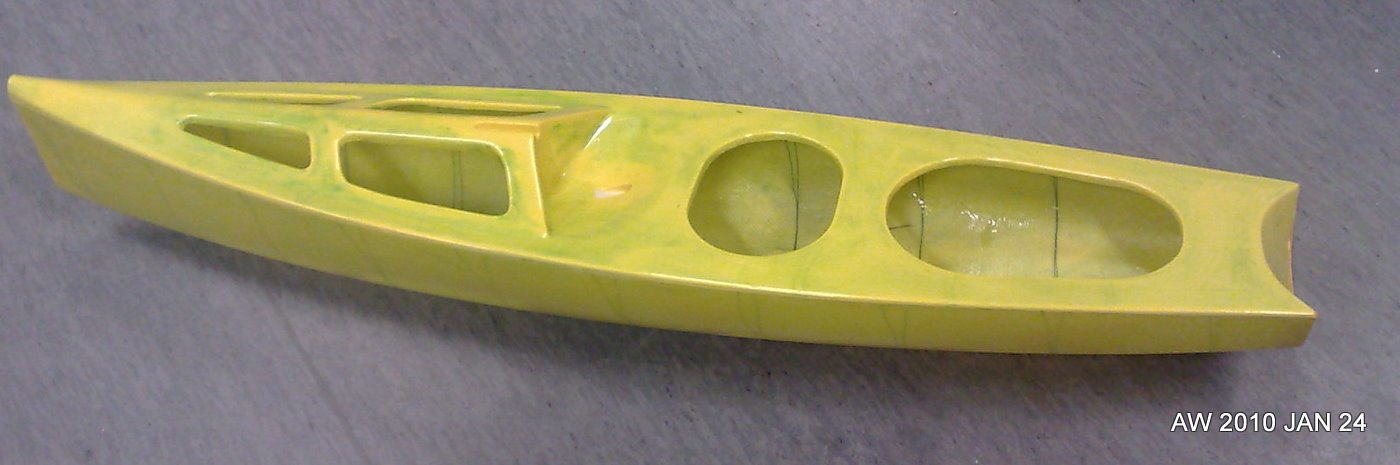
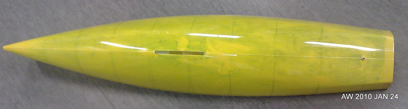
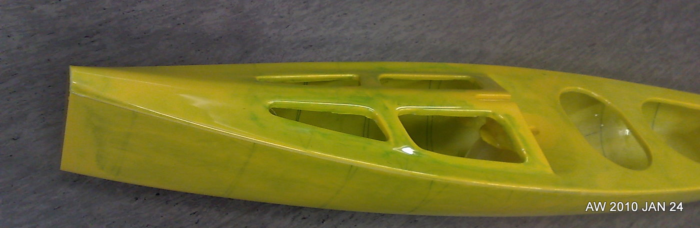
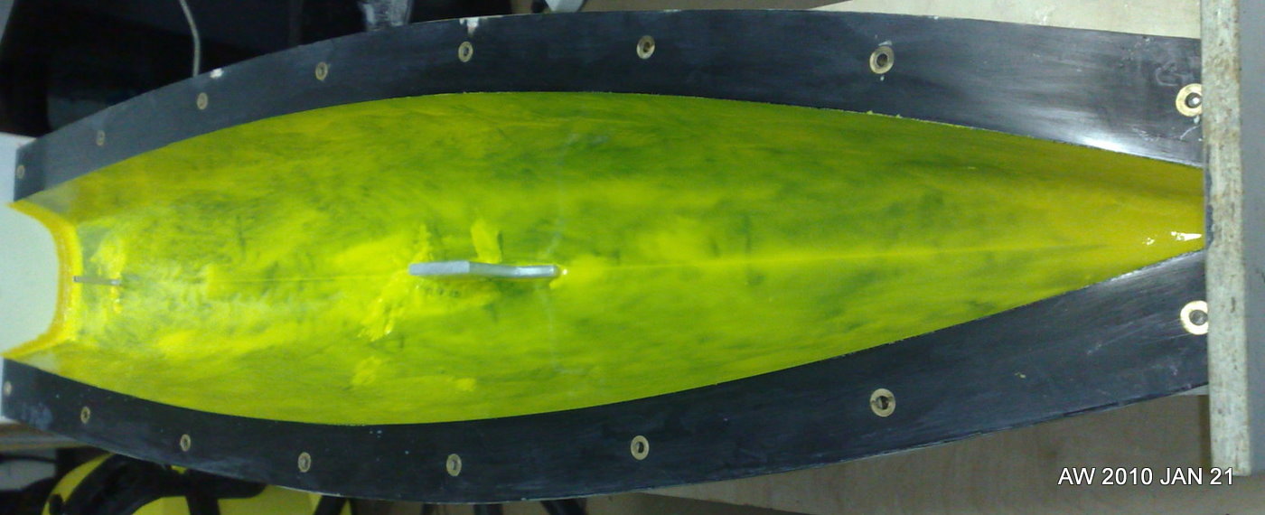
Pikanto hull nr 3
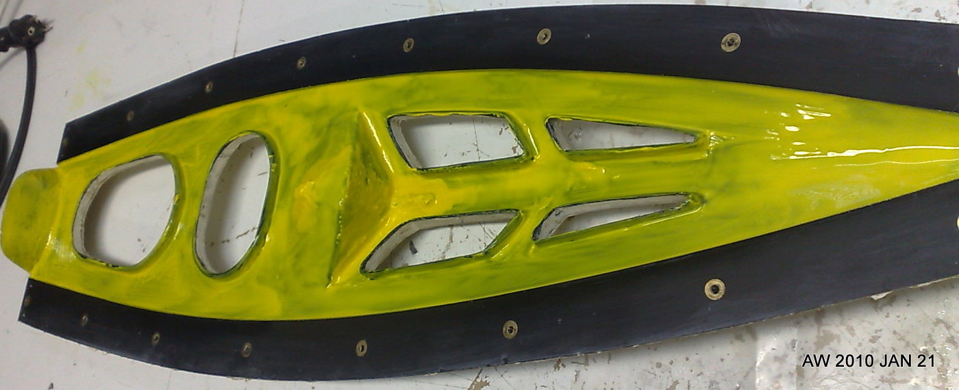
Our third PIKANTO hull, a.k.a. "Yellow Submarine" was taken out of the mould today. As expected, the yellow gelcoat doesn't cover very well which gives the boat a very "prototype" and/or "artsy" look 🙂
I used a dremel with a cutting-wheel to cut off the extra glassfiber from the deck openings, and then a sharp knife and sandpaper to finish the join between the hull halves and between the deck and the hull.
For various reasons it seems hulls nr1 and nr2 will be demo-boats, and nr3 will be the first one to sail. Weight is slightly more than before, 620 g. As predicted, by hull nr 5 or so we will have mastered at least the basics of how to produce nice looking strong and light hulls from these moulds.
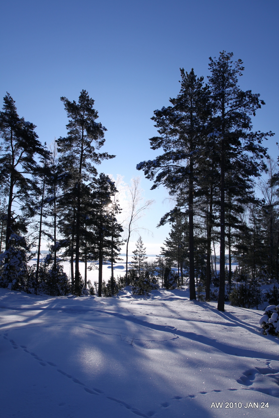
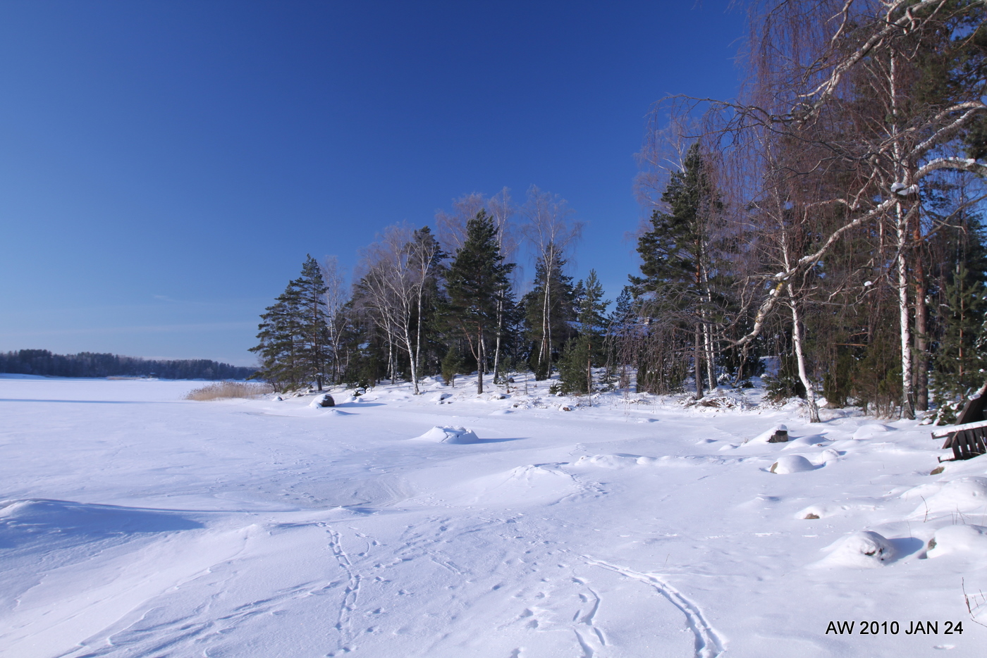
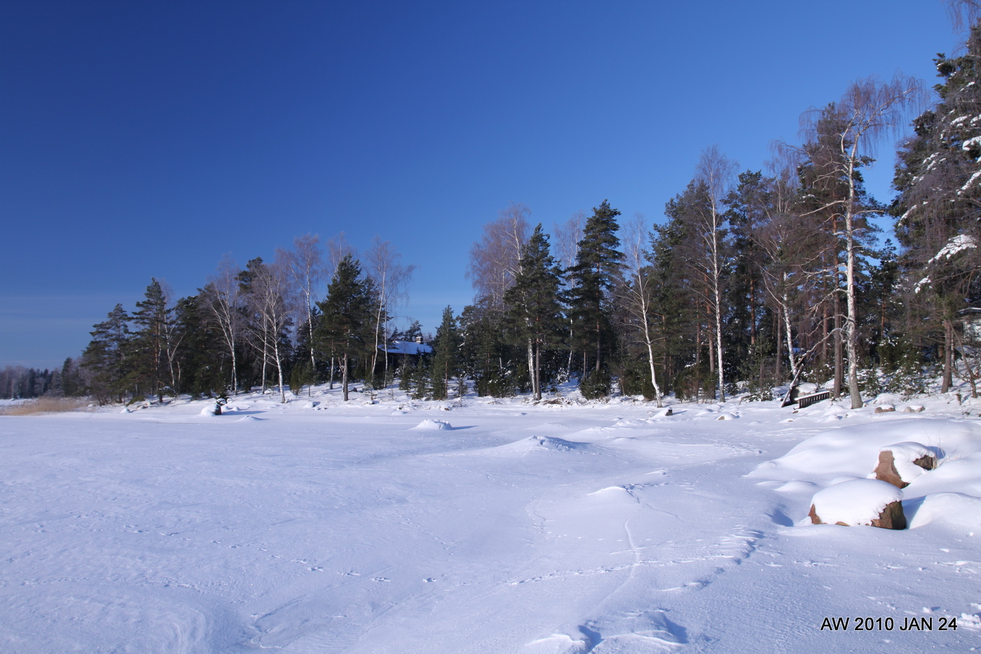
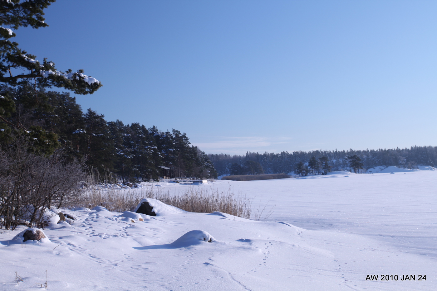
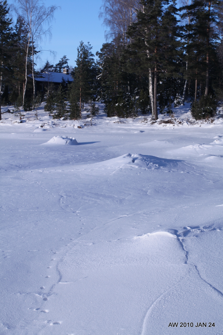
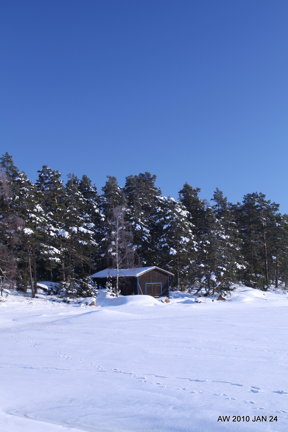
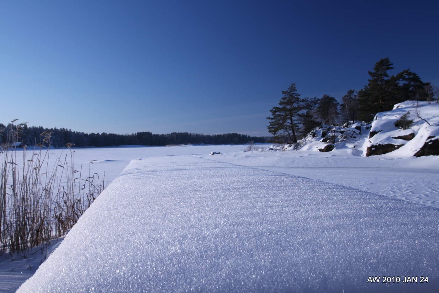
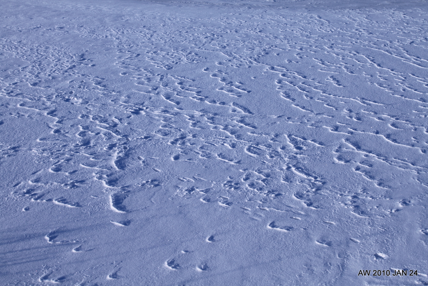
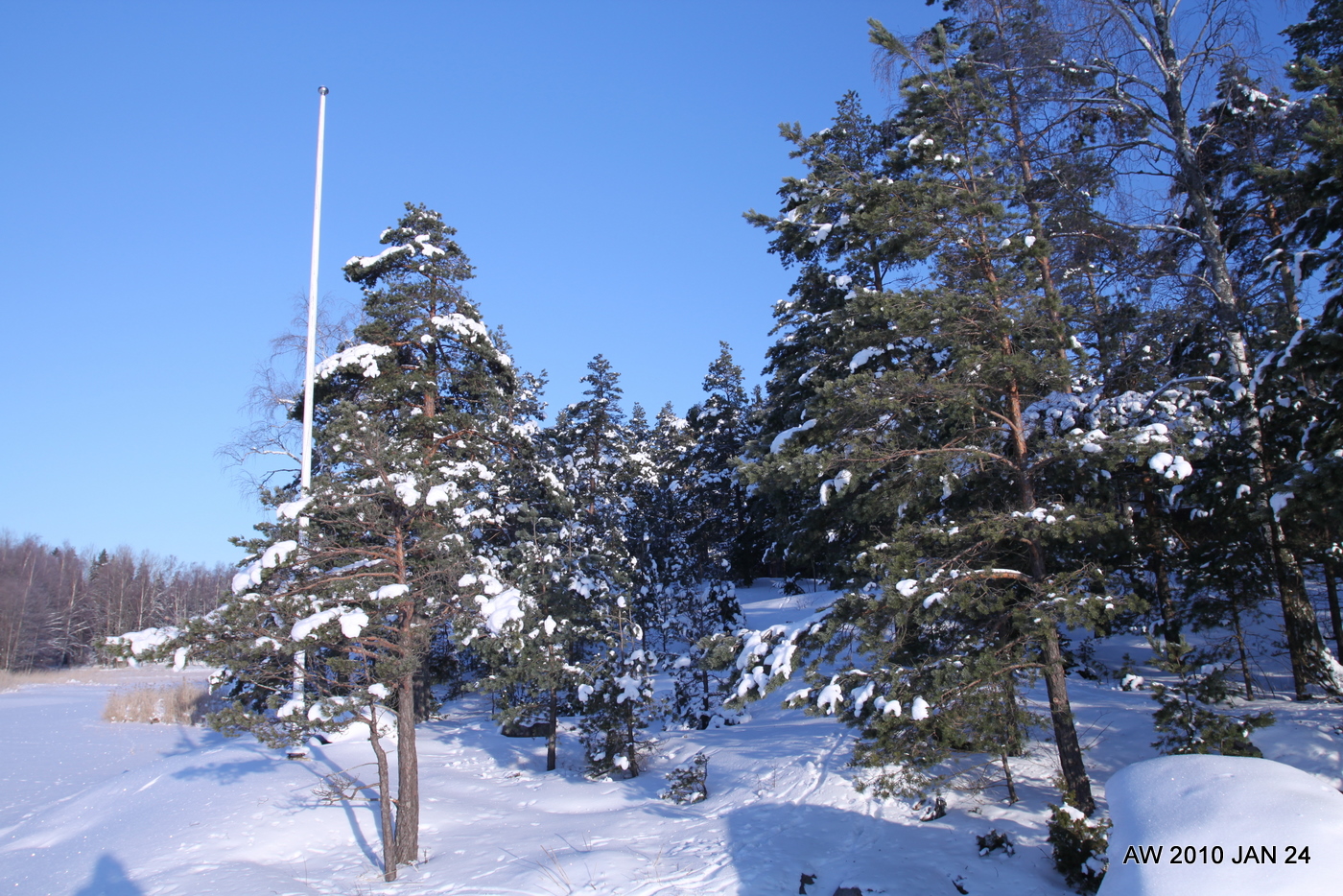
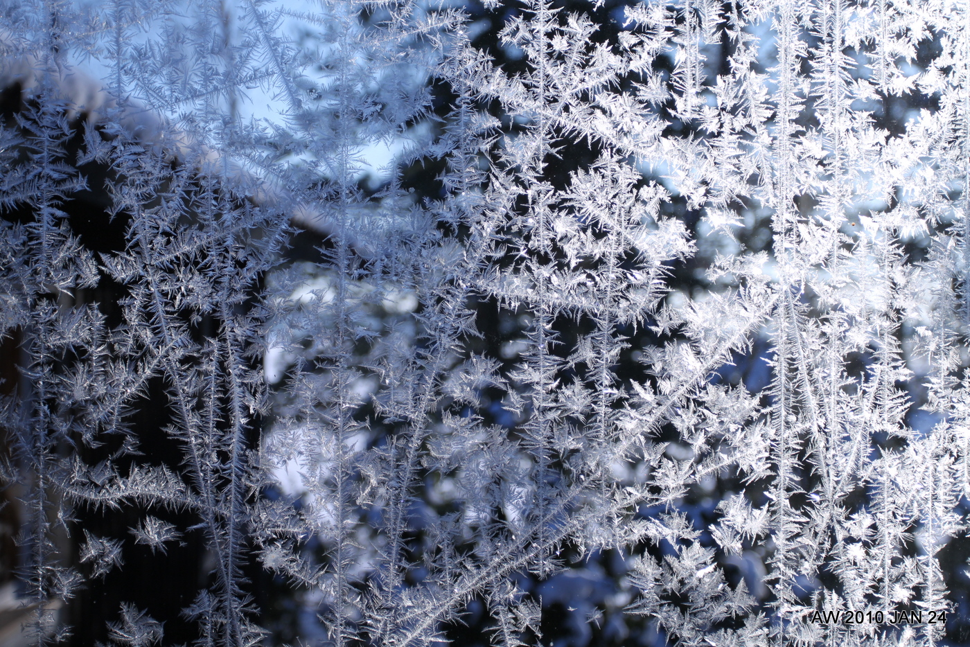
Winter Wonderland
I took some astro-photos on Sat-Sun night, and then these "winter wonderland" pictures on Sunday morning. -15 C is not cold or unpleasant if you dress well and keep moving and generating heat. If you stand still or the wind is blowing then anything colder than -10 C is miserable. Shot with the 17-40/4L and a circular-polarizer(*) (from Dealextreme), which produces very nice deep blue skyes, and a gradient in the wider shots from almost white to dark blue. Something to practice with more in the future.
Astrophotos will appear when I have time to process them. Also stay tuned for "yellow submarine" fresh out of the mould!


Nerdy Physics Note:
(*) There's no such thing as a "circular-polarizer", in the sense that a single optical element would only pass circularly polarized light (AFAIK), and what they sell in stores as "circular-polarizers" should of course be called a "linear polarizer followed by a quarter-wave plate", but I guess "circular-polarizer" is just shorter and easier. The quarter-wave plate is there because the autofocus system on many cameras uses polarizing beam-splitters for different paths of the beam, so a simple linear polarizer would sometimes cause the autofocus to fail.
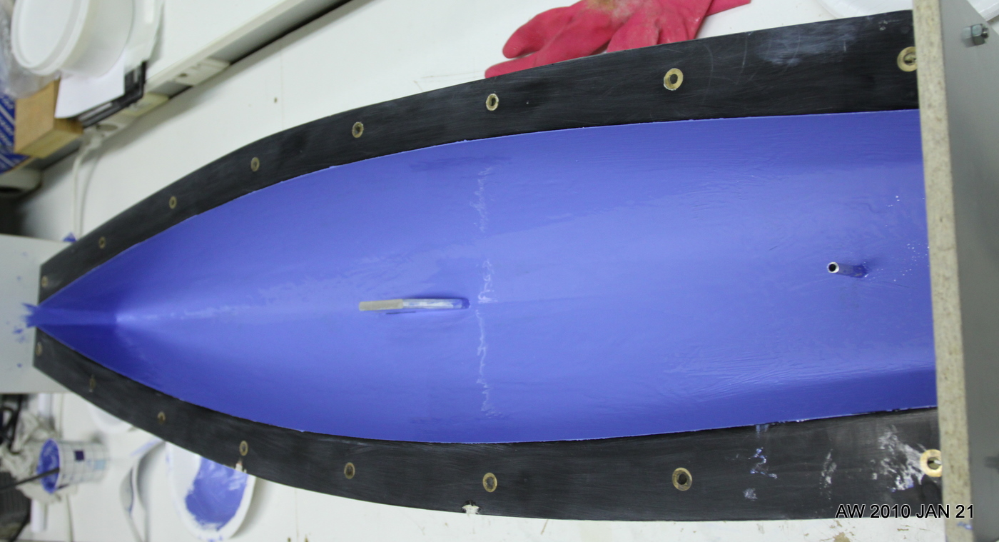
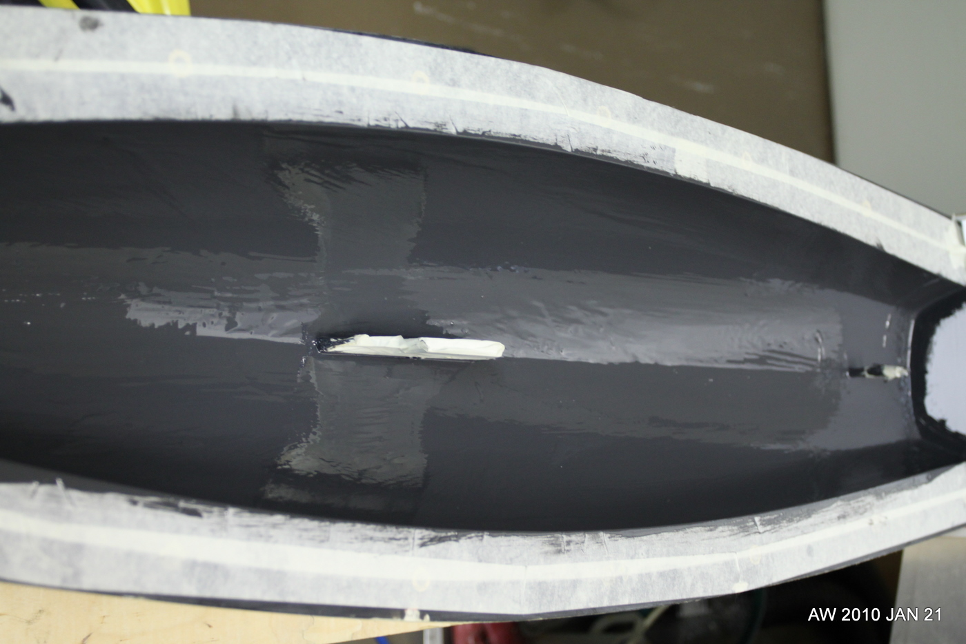
Yellow Submarine
We are finding that different colour pastes result in gelcoats with widely different ability to cover and produce a nice finish. This means we'll have to do a bit of experimenting and then only produce boats with colours that are easy to work with.
Hull nr. 3 "Yellow Submarine" was moulded last weekend and it will be interesting to see the result. Against the black of the mould-gelcoat the yellow doesn't seem to cover too well (compare to hulls 1 "sky-blue" and 2 "battleship-grey").
These pictures are taken just after painting the gelcoat into the mould. We make the gelcoat from the moulding-resin by adding colloidal silica and the colour paste.
Making hull nr3 was a 7 hour process:
10:00 arrive at workshop, do a bit of cleaning and preparation
11:00 start mixing and applying gelcoat to moulds, takes about an hour for deck and hull.
12:00 - 14:00 wait... gelcoat is in the mould and needs to cure. not much to do now(eat lunch, cut fibers, etc).
14:00 start moulding. The hull is fairly quick and only takes an hour or so
15:00 mould deck. This is more tricky with a lot of different small bits of fibers required, takes more than an hour usually
~16:00 fibers are in both moulds, close the moulds and start on the join between deck and hull
17:00 all done. Leave moulds and new boat to cure.
DHL FAIL
Geography according to DHL: The most economical/effective/quick way to ship something from Arlanda to Helsinki is via... Leipzig, Germany. FAIL.


Links - 2010 Jan 21
- Bell Labs vs. the LHC -
- Boat Launch Fail -
- Sapper, Stradivarius and Skylight -
- David Hill discusses Lenovo Skylight smartbook design -
- Active-passive calibration of optical tweezers in viscoelastic media -
- Note: Interference technique for minimally invasive, subnanometer, microsecond measurements of displacements -
Connectors

Drilled four holes for AMP-connectors and used a hole-punch to make cut-outs for eight 25-pin D-connectors. The four motor-connectors will provide 3-phase power to the spindle-servo, the X- and Z-servos, and a high-speed live-tool spindle. The servos have three Hall-signals and three(single-ended) or six(differential) encoder signals which will enter the cabinet through the D-connectors. I'm using these since I'll use 25-pin printer-cables for the Hall/Encoder signals. There are eight D-connectors just to provide some room for expansion. Three will be in immediate use for the three servos, one for limit/home switches, and one or two will be used for a jog-pendant. That still leaves three 25-pin connectors unused (tool-changer? tool-length probe? etc.)
Also mounted the breakout-boards inside:

Mesa 5i20 breakout boards

In 2006 I made optoisolator cards for the cnc-mill project, but now with the lathe I am using servo-drives and a VFD which mostly already have optoisolated inputs, so I will use these very simple breakout boards instead. There are two pitch-standards for the screw-terminals, an imperial one with a pitch of 5.08 mm (i.e. 0.2 inches), and a metric one with 5.0 mm pitch. These boards are for 5.0 mm.
Pads logic and layout files: 2010_01_16_m5i20_breakout_board
Etch-mask (PDF): etch-mask
