More Medial-Axis pocket milling

My first attempt at MA-pocketing only worked when the medial axis of the pocket was a tree (a connected acyclig graph).

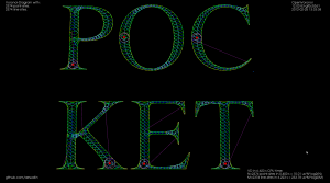
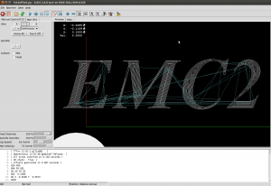
I've now extended this to work with pockets consisting of many parts which ha a MA consisting of multiple connected components. There's also simple support for when the MA has cycles, such as seen in "P" and "O" above. With a large cut-width the toolpath looks like this:

Each component of the pocket starts at the red dot with a pink spiral that clears the largest MIC of the pocket. The rest of the pocket is then "scooped out" using green cut-arcs connected with cyan (tool down) or magenta (tool up, at clearance height) rapid moves.

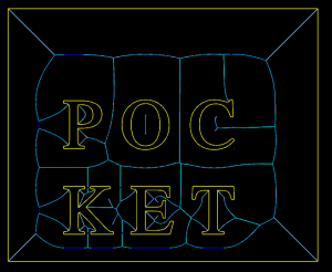
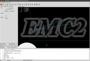
Instead of clearing the interior of letters we can also clear a pocket around the letters. The MA then looks like this:

This video shows quite a lot of "air-cutting". This is because the algorithm only keeps track of the previously cleared area behind the MIC that is currently being cleared. When we come to the end of a cycle in the MA the algorithm does not know that in fact MICs in front of the current MIC have already been cleared.

Medial-Axis pocketing

Update: In the US, where they are silly enough to have software-patents, there's US Patent number: 7831332, "Engagement Milling", Filing date: 29 May 2008, Issue date: 9 Nov 2010. By Inventors: Alan Diehl, Robert B. Patterson of SURFWARE, INC.

Any pocket milling strategy will have as input a step-over distance set at maybe 10 to 90% of the cutter diameter, depending on machine/material/cutter. Zigzag and offset pocketing paths mostly maintain this set step-over, but overload the cutter at sharp corners. Anyone who has tried to cnc-mill a hard material (steel) using a small cnc-mill will know about this. So we want a pocketing path that guarantees a maximum step-over value at all times. Using the medial-axis it is fairly straightforward to come up with a simple pocketing/clearing strategy that achieves this. There are probably many variations on this - the images/video below show only a simple variant I hacked together in 2-3 days.

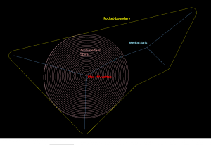
The medial-axis (MA, blue) of a pocket (yellow) carries with it a clearance-disk radius value. If we place a circle with this radius on the medial-axis, no parts of the pocket boundary will fall within the circle. If we choose a point in the middle of an MA-edge the clearance-disk will touch the polygon at two points. If we choose an MA-vertex of degree three (where three MA-edges meet), the clearance-disk will touch the pocket at three points.

MA-pocketing starts by clearing the largest clearance-disk using a spiral path (pink).

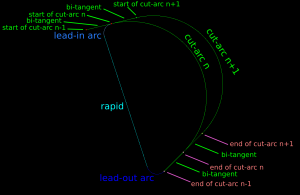
From the maximum clearance-disk we then proceed to clear the rest of the pocket by making cuts along adjacent clearance-disks. We move forward along the MA-graph by an amount that ensures that the step-over width will never be exceeded. The algorithm loops through all clearance-disks and connects the arc-cuts together with bi-tangents, lead-out-arcs, rapids, and lead-in-arcs.

This video shows how it all works (watch in HD!). Here the cutter has 10mm diameter and the step-over is 3mm.

I'll try to make a variant of this for the case where we clear all stock around a central island next. These two variants will be needed for 3D z-terrace roughing.

Towards medial-axis pocketing

Update: some work on connecting MICs together with bi-tangent line-segments, as well as a sequence of lead-out, rapid, lead-in, between successive MIC-slices:

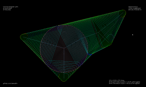
It gets quite confusing with all cutting and non-cutting moves drawn in one image. The path starts with an Archimedean spiral (pink) that clears the initial largest MIC. We then proceed to "scoop" out the rest of the pocket with circular-arc cutting moves (green). At the end of a scoop we do a lead-out-arc (dark blue), followed by a linear rapid (cyan), and a lead-in-arc (light blue) to start the next scoop.

Next I'd like to put together an animation of this. The overall strategy will be much clearer from a movie.

This animation shows MICs, i.e. maximal inscribed circles (green, also called clearance-disks), inside a simple polygon (yellow). The largest MIC is shown in red.

This is work towards a new medial-axis pocketing strategy. The largest MIC (red) is first cleared using a spiral strategy. We then proceed to clear the rest of the pocket in the order that the MICs are drawn in the animation. We don't have to spin the tool around the whole circle. only the parts that need machining, which is the part of the new MIC that doesn't fall inside the previously machined MIC. As mentioned in my previous post this is inspired by Elber et al (2006).

The next step is to calculate how we should proceed from one MIC to the next, and how we do the rapid-traverse to re-position the tool for the next cut.

See also the spiral-toolpath by Held&Spielberger (2009) or their 199-slide presentation. The basics of this spiral-strategy is a straightforward march along the medial-axis. But then a filtering/fitting algorithm, which I don't have at hand right now, is applied to get the smoothed spiral-path.

Rendering an image with VTK

For exploring and visualizing various pocketing or area-clearing milling toolpath strategies I am thinking about reviving the "pixel-mowing" idea from 2007. This would be simply a bitmap with different color for stock remaining and already cleared area. It would be nice to log and/or plot the material removal rate (MRR), or the cutter engagement angle. Perhaps graph it next to the simulation, or create a simulated spindle-soundtrack which would e.g. have a pitch proportional to the inverse of the MRR. It should be possible to demonstrate how the MRR spikes at sharp corners with classical zigzag and offset pocketing strategies. The solution is some kind of HSM-strategy where the MRR is kept below a given limit at all times.
My plan is to play with maximally-inscribed-circles, which are readily available from the medial-axis, like Elber et. al (2006).

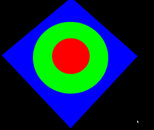
Anyway the first step is to render a bitmap in VTK, together with the tool/toolpath, and original pocket geometry:

import vtk
import math
 
vol = vtk.vtkImageData()
vol.SetDimensions(512,512,1)
vol.SetSpacing(1,1,1)
vol.SetOrigin(0,0,0)
vol.AllocateScalars()
vol.SetNumberOfScalarComponents(3)
vol.SetScalarTypeToUnsignedChar()
 
scalars = vtk.vtkCharArray()
red = [255,0,0]
blue= [0,0,255]
green= [0,255,0]
for n in range(512):
    for m in range(512):
        x = 512/2 -n
        y = 512/2 -m
        d = math.sqrt(x*x+y*y)
        if ( d < 100 ):
            col = red
        elif (d<200):
            col = green
        else:
            col = blue
        for c in range(3):
            scalars.InsertTuple1( n*(512*3) + m*3 +c, col[c] )
 
vol.GetPointData().SetScalars(scalars)
vol.Update()
 
ia = vtk.vtkImageActor()
ia.SetInput(vol)
ia.InterpolateOff()
 
ren = vtk.vtkRenderer()
ren.AddActor(ia)        
renWin = vtk.vtkRenderWindow() 
renWin.AddRenderer(ren)
 
iren = vtk.vtkRenderWindowInteractor()
iren.SetRenderWindow(renWin)
interactorstyle = iren.GetInteractorStyle()
interactorstyle.SetCurrentStyleToTrackballCamera()     
 
camera = vtk.vtkCamera()
camera.SetClippingRange(0.01, 1000)
camera.SetFocalPoint(255, 255, 0)
camera.SetPosition(0, 0.1, 500)
camera.SetViewAngle(50)
camera.SetViewUp(1, 1, 0)
ren.SetActiveCamera(camera)
iren.Initialize()
iren.Start()

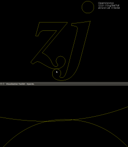
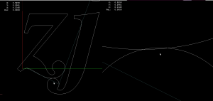
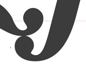
With FreeSerifBoldItalic, don't ever write "zj"!

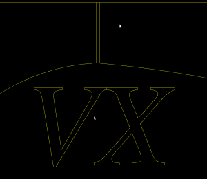
Update: Here is "VX" with FreeSerifItalic. There is overlap in LibreOffice also.

For the most part truetypetracer produces valid and nice input data for testing openvoronoi. But sometimes I see wiggles, and now this:

It is frustrating to try to track down bugs in downstream algorithms that take this as input, and assume all line-segments are non-intersecting when in fact the are not!

I seem to have only 13 .ttf files in my /usr/share/fonts/truetype/freefont folder, but maybe there are more elsewhere. I should find a font that is properly designed without wiggles and without overlaps. The other approach is to write a pre-processor that looks at input data and either rejects or cleans it. Looking for all pair-wise intersections of N line-segments is a slow N^2 algorithm - at least for a naive implementation (without bounding-boxes or binning or other tricks).

Unlike the wiggles, this overlap doesn't happen in Inkscape:

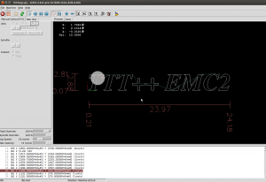
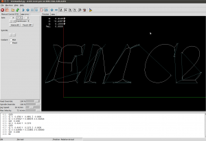
Here is G-code generated with ttt-4.0 and drawn in LinuxCNC:

Here is a screenshot from LibreOffice 3:

and GIMP:

Non-smooth output from ttt

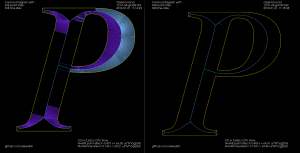
I tried cranking up (10-fold) the number of line-segments that are used when approximating conics and cubics with lines. The results are mostly OK, but sometimes "wiggles" or "S-curves" appear, which cause problems for the medial-axis filter. This "P" is an example:

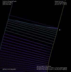
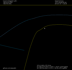
The medial axis on the right does not look correct. If we zoom in it's clear that there's an "S-curve" in the input geometry, which causes a LINELINE edge (drawn in darker blue), which the medial-axis filter doesn't think should be removed:

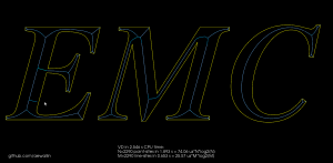
For the letters "EMC" it looks mostly OK, but there's a similar wiggle in "E"


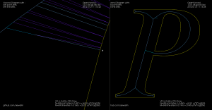
Increasing the number of line-segments further causes even stranger things. Here's a zoom-in at the top of "P" that shows both the wiggle that was visible before, but also a strange inward bulge:

Hopefully this is a bug in how conics/cubics are converted to line-segments in ttt, and not an issue with how FreeType fonts are represented.

EMC2 Filters

I hacked together a few python-scripts that can be run as "filters" in EMC2. They are opened/run from AXIS and produce G-code into EMC2.

The first one is ttt2ngc which simply demonstrates my C++ port of Chris Radek's truetype-tracer. The original code is a rather monolithic C-program while my C++ port is divided into smaller files and offers python-bindings and more options (for example arc, cubic, conic output can be turned on/off independently).

The seconds script is ttt2offset which takes ttt-geometry, builds a VD, and produces offsets. By reversing the list of points from ttt either inwards or outwards offsets can be produced. Currently the toolpaths are machined in the order they are produced, i.e. in order of increasing offset value. An improvement would be to order the loops so that for e.g. pocketing the innermost loop is machined first, and rapid-traverses are minimized.


The third script is ttt2medial. Here the VD is filtered down to an (approximate) medial-axis, and the edges of the medial axis are chained together into a toolpath. The chaining-algorithm could probably be improved much, again to minimize rapid-traverses.

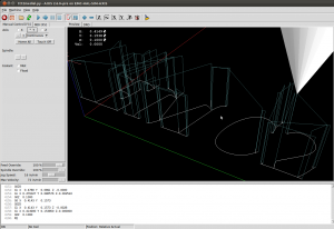
If this is run with a V-shaped cutter with a 90-degree angle we can push the cutter into the material by an amount equal to the clearance-disk radius of the edge. This is a "V-carving" toolpath which should produce a cut-out very similar to the outline of the font. For added effect choose a material with  contrasting surface and interior colors.

It would be interesting to know if this v-carving g-code is anywhere near to correct. If someone has a cutting-simulator, or is adventurous enough to run this on an actual machine, I'd be very interested in the results! (here is the g-code: emc2_vcarve.ngc)

Here is a metric version. The max depth is around -3mm, so a 10mm diameter 90-degree V-cutter should be OK. The text should be roughly 100mm long: emc2_vcarve_mm_ver2.ngc

Disclaimer: This is experimental code. Warnings, Errors, and Segfaults are common.

Graph filters

I've put together two graph filters that can be applied to the VD.

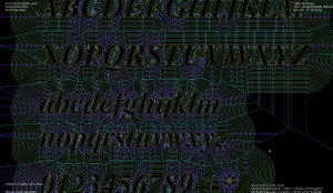
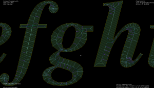
The first one detects the interior or exterior of a polygon. When the VD is constructed the polygon boundary must be input in CW order, and any islands inside the polygon in CCW order (or vice versa). This allows running other downstream algorithms only on the parts of the VD that pass the filter. Like these exterior and interior offsets:
 

The other filter looks at the interior VD and tries to produce an approximate medial axis. We can start with the complete interior VD, such as this "J":
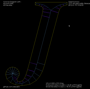
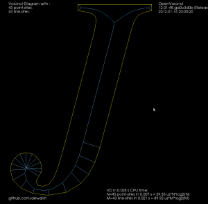
By definition the medial axis consists of "the set of all points having more than one closest point on the object's boundary". The separator edges shown in purple above can clearly be eliminated, since their adjacent/defining sites are an open line-segment and the segment's endpoint. Removing separators gives us this:
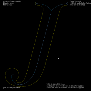
Now we can either finish here, or try to filter out some more edges to make it look better. Since we approximated smooth curves with line-segments we should try to detect which parts of the boundary are really distinct curves, and which are merely many consecutive line-segments approximating a single smooth curve. I've compared the dot-product (angle) between two consecutive segments, and applied an arbitrary threshold:
For the whole alphabet it looks like this.
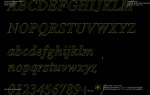
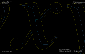
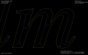
The choice of threshold value for the angle-filtering is arbitrary. In many cases such as "x" and "m" it results in small or large left-over branches. This could probably be avoided by (1) tuning the angle-threshold, (2) approximating smooth curves with a larger number of line-segments, (3) eliminating branches below a certain length, or (4) choosing a font that's made for v-carving (are there any?).
 

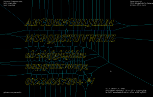
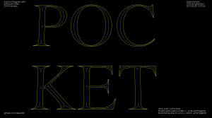
Although it's probably not right to call it a "medial axis" , the same filter applied to the exterior VD also looks interesting. It divides the plane into organic looking shapes around each letter. It could probably be used for a lot of shape analysis. For example in a smart pocketing routine to find large areas that can be cleared with a large cutter, before a smaller cutter is required for the details. Note that in addition to the geometric shape of all the blue-ish edges the diagram also holds distance-information at each point of an edge. The distance stored is a clearance-disk radius, i.e. we can draw a circle at any point of an edge with this radius, and no input geometry (in yellow) will intersect the circle.
2D Offsets

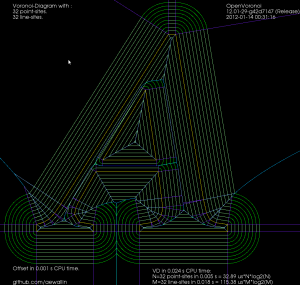
Once we have a VD it is almost trivial to calculate 2D offsets. While the VD for n line-segments takes O(n*log(n)) time to calculate, the offset-generation is a simple "march" that takes O(n) time. In this "A" example it takes 24 milliseconds to calculate the VD and less than 1 millisecond to produce all the shown offsets. Input geometry in yellow, VD in blue. Offset lines in light-green and offset arcs in slightly darker green.

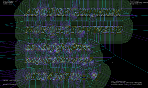
Here is a larger example where VD takes 1.3 seconds, and all offsets shown take 99 milliseconds in total to produce. It would be interesting to benchmark this against libarea or other open-source 2D offset solutions. (here all line/arc offsets in one green color, for simplicity)

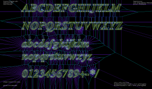
Here is a third picture with offsets for a single offset-distance: