Installing the latest KiCAD on Ubuntu 14.04LTS

Add the ppa:js-reynaud/ppa-kicad to your list of sources:

sudo add-apt-repository ppa:js-reynaud/ppa-kicad

Then update package repository info

sudo apt-get update

Then install kicad

sudo apt-get install kicad kicad-common

Done. As of 2014-10-19 I get "Build 2014-jul-16 BZR unknown" - which should be new enough to contain most of the features I want.

There is a problem with this install because the environment variable KIGITHUB is not set. We do that by adding this line to ~/.profile

export KIGITHUB="https://github.com/KiCad"

For this to take effect you need to log out and then log in again. You should now see KIGITHUB defined in the under Preferences/Library Tables in Pcbnew. I still have KISYSMOD undefined, but that doesn't seem to matter(?).

So far so good. Next stop is learning how to work with the kicad github plugin so I can store my own symbols/footprints in my own github repo.

TEC-Drive v2

Sadly TEC-Drive v1 died an untimely death when it overheated due to being powered from +/-15 V instead of the designed +/-5 V.

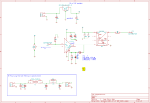
TEC-Drive v2 is a simplified design using TO-220 packaged LM317/LM337 adjustable regulators and the OPA569 high-current op-amp.

tecdrive_v2_schematic

Constant-current drive is achieved using the OPA569 (U2) I_monitor output. I_monitor sources/sinks a fraction I_out/475 of the actual output current. By using another op-amp (U1) in a transimpedance configuration we get a feedback-voltage proportional to the output current.

PCB layout on a 100 mm x 160 mm eurocard:

tecdrive_v2_pcb


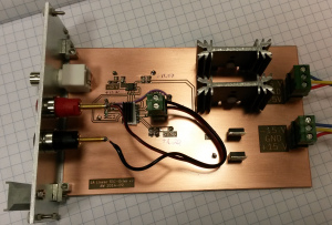
Built and assembled as a plug-in card for a 3U rack. Note big heatsinks on the +/-2.5 V regulators.

tecdrive_v2_assembled

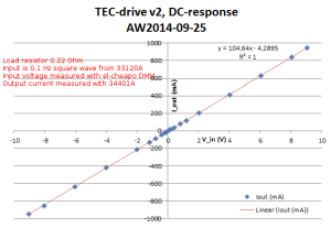
The DC-response is I_out = 105 mA/V * V_in, with an offset at zero-input of -4 mA.

tecdrive_v2_dc-response

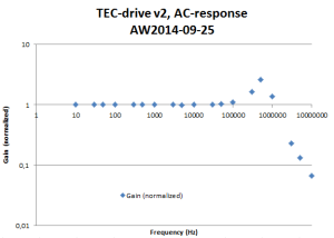
With no low-pass capacitors (C1 at the input, and C11 over the transimpedance-resistor) added and a purely resistive load the frequency response extends beyond 1 MHz with some ringing.

tecdrive_v2_ac-response

Pulse Stretcher - V2

Update: kicad files: 2014-07-23-pulse_stretcher_kicad

A development on pulse stretcher V1.

This circuit is used to stretch a short 10 ns pulse from a photon-counting module to a 100ns long pulse that can be more easily recorded or time-stamped e.g. with the white rabbit fine-delay FMC.

pulse_stretch_schematic_2014-06-30

The new circuit is the same LT1711-based design as the old one, with an added buffer (BUF602) on the output. This improves output-load handling because the BUF602 can drive both 50 Ohm and 1 MOhm loads.

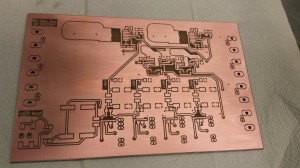
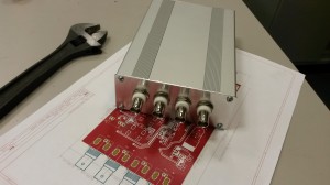
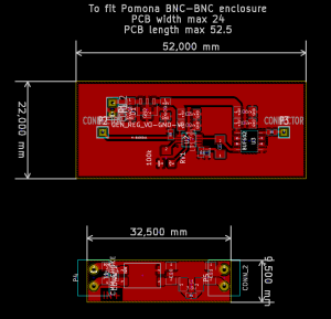
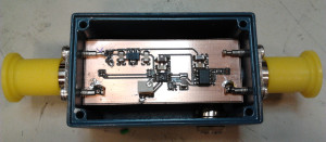
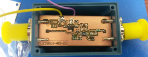
The PCB is made to fit a BNC-BNC enclosure by Pomona.

pulse_stretch_2014-06-30

pulse_stretcher_assembled

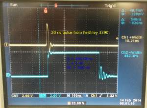
Some testing with an artificial input-pulse from a Keithley 3390 signal-generator..

pulse_stretcher_test_keithley3390

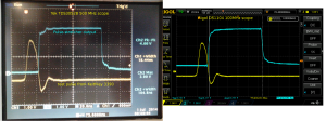
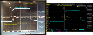
.. and with the actual PMT-pulse. Note how the 100MHz scope produces nice round smooth signals while the 500 MHz Tektronix reveals more of the ugly truth.

pulse_stretcher_test_PMT

ADF4350 PLL+VCO and AD9912 DDS power spectra

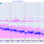
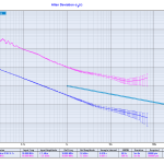
Update 2015-09-28: ADEV and Phase-noise measured with a 3120A:


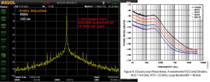
Here's the 1 GHz output of an ADF4350 PLL+VCO evaluation board, when used with a 25 MHz reference.

The datasheet shows a phase noise of around -100 dBc/Hz @ 1-100 kHz, so this measurement may in fact be dominated by the Rigol DSA1030A phase noise which is quoted as -88 dBc/Hz @ 10 kHz.

1GHz_adf4350_output_with_25MHz_ref-input

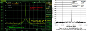
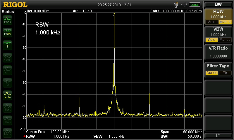
The 1 GHz output from the ADF4350 is used as a SYCLK input for an AD9912 DDS. The spectrum below shows a 100 MHz output signal from the DDS with either a 660 MHz or 1 GHz SYSCLK. The 660 MHz SYSCLK is from a 10 MHz reference multiplied 66x by the AD9912 on-board PLL. The 1 GHz SYSCLK is from the ADF4350, with the AD9912 PLL disabled.

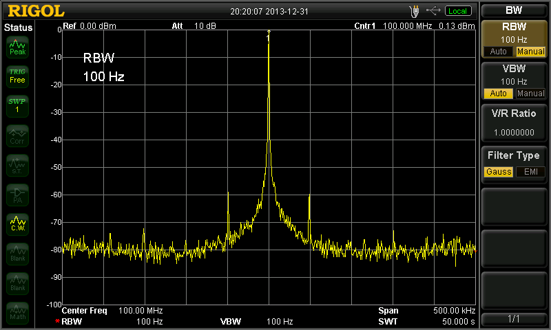
The AD9912 output is clearly improved when using an external 1 GHz SYSCLK. The noise-floor drops from -80 dBm to below -90 dBm @ 250 kHz from the carrier. The spurious peaks at +/- 50 kHz disappear. However this result is still far from the datasheet result where all noise is below -95 dBm just a few kHz from the carrier. It shouldn't matter much that the datasheet shows a 200MHz output while I measured a 100 MHz output.

Again I suspect the Rigol DSA1030A's phase-noise performance of -88dBc/Hz @ 10 kHz may in fact significantly determine the shape of the peak. Maybe the real DDS output is a clean delta-peak, we just see it like this with the spectrum analyzer?

100MHz_AD9912_internal_vs_external_PLL

Martein/PA3AKE has similar but much nicer results over here: 1 GHz refclock and 14 MHz output from AD9910 DDS. Amazingly both these spectra show a noise-floor below -90 dBm @ 50 Hz! Maybe it's because the spectrum analyzer used (Wandel & Goltermann SNA-62) is much better?

DDS Front Panel

Two of these 1U 19" rack-enclosure front panels came in from Shaeffer today. Around 70 euros each, and the best thing is you get an instant quote on the front panel while you are designing it with their Front Panel Designer software. The box will house an AD9912 DDS.

dds_panel_0

From left to right: 10 MHz reference frequency input BNC, DDS output BNC, 40mm fan (1824257 and 1545841), 20x2 character LCD (73-1289-ND), rotary encoder with pushbutton (102-1767-ND), and rightmost an Arduino Due (1050-1049-ND) with Ethernet shield (1050-1039-ND). The panel is made to fit a Schroff 1U enclosure (1816030) with the inside PCBs mounted to a chassis plate (1370461).

dds_panel_1

Here's a view from the inside. I milled down the panel thickness from 4 mm to around 2.5 mm on the inside around the rotary encoder. Otherwise all components seem to fit as designed.

dds_panel_2

Next stop is coding an improved user-interface as well as remote-control of the DDS and PLL over Ethernet.

Pulse Stretcher - v1

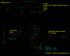
A first try at this pulse stretcher circuit based on the LT1711 comparator. I need it for stretching a short 10ns pulse from a PMT.

stretcher_sch_2014-02-13

The idea is to use the output latch of the LT1711. Once the output goes high, the combination C4 R4 keeps the latch pin (and thus the output) high for a time R*C. The Schottky diode is there to prevent the latch pin from swinging to far negative once the output goes low.

stretcher_pcb_2014-02-13

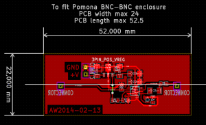
The PCB is made to fit into a BNC-BNC enclosure such as the ones from Pomona.

pulse_stretcher_prototype

Messing up the pin-order of voltage regulators is becoming a habit! Note how the regulator is mounted the wrong way round compared to the PCB design - because I had the pin order wrong in my schematic.

pulse_stretcher_input_output

I used a Keithley 50 MHz function generator to generate a 20ns long input pulse (the shortest possible from the Keithley) and the pulse-stretcher outputs a ca 483 ns output pulse. The prototype used a 1 nF capacitor with a 500 Ohm resistor which gives a nominal time-constant of 500 ns. The output pulse duration is far from constant and varies quite a bit from pulse to pulse.

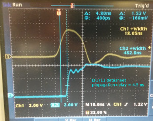
pulse_stretcher_propagation_delay

This verifies that the propagation delay of the LT1711 in this circuit is within specifications, ca 4.5 ns. In addition to the comparator there is also maybe 70 mm of BNC-connectors, wires, and PCB-traces in the signal path, but that would add only ~350 ps to the propagation delay (assuming 2e8 m/s signal velocity).

One problem with this design is that it is sensitive to the load impedance connected to the output. With a 1 MOhm setting on the oscilloscope the pulse-length is correct, but switching to a 50 Ohm load impedance allows the capacitor to discharge significantly through the load impedance.

Version 2 of this circuit should thus add an output buffer (fast, low-jitter!) that can drive both 1 MOhm and 50 Ohm loads. An adjustable trigger level for the -Input of the LT1711 comparator could also be useful.

AD9912 DDS Test

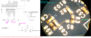
Update: it turns out the PLL filter components were not connected at all during the first tests I did 🙂 Here's a picture that compares the schematic against the actual board. When I changed the 0R resistor from position "R3" to position "R5"  the PLL started behaving much more nicely. If anyone from AD is reading - please update your documentation!

ad9912_eval_board_pll_schematic

With this change, and a 66x PLL multiplier giving a 10MHz x 66 = 660 MHz SYSCLOCK I get quite nice output:

Fout100M_Span50M Fout100M_Span400M Fout100M_Span500k

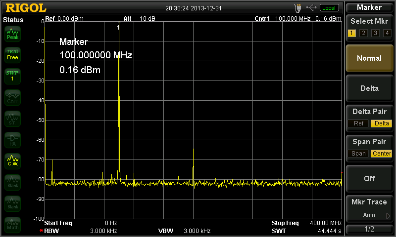
The output is set to 100 MHz and has an amplitude of ~0 dBm. There are -60 dBm spurs at +/- 50 kHz (not sure why?), -70 dBm spurs at +/- 10MHz, and a -65 dBm second harmonic at 200 MHz.

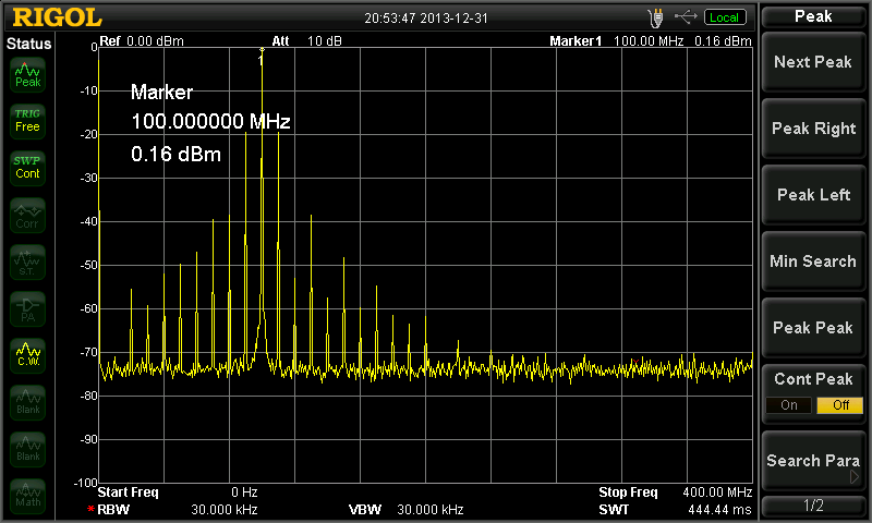
If I activate the "2x Reference" setting which detects both rising and falling edges of the input clock, and use that with a 40x PLL for a 10MHz x2 x40 = 800 MHz SYSCLOCK I still get very strong spurs at 10 MHz:

Fout100M_Span400_PLL_2x40x

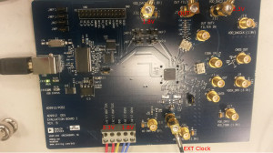
I have been testing this AD9912 DDS evaluation board:
ad9912_evkit_pcb_text

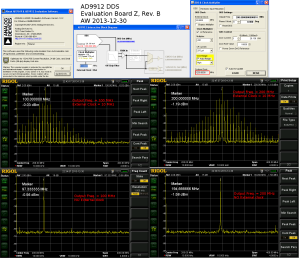
So far the results are a bit strange, with output as advertized only when no external input clock is supplied. Strange.

dds_test_2013-12-30

DC-Bias Amplifier

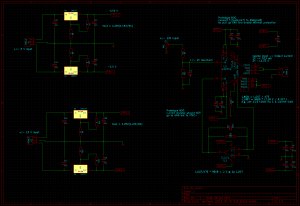
I've put together the first version of a DC-bias amplifier used for applying four DC-voltages to the trim electrodes of an ion trap. The axial voltages required are low, and they are applied symmetrically as +Vz and -Vz. The transverse voltages (X and Y) however can be as high as 100 V. Two high-voltage op-amps PA340CC are used for the X and Y channels, while the -Z and +Z output voltages are produced by two OPA454 op-amps. The amplifier has three +/-10 V inputs (Vx, Vy, Vz), and produces four outputs designed to be 10*Vx, 10*Vy, -Vz, and +Vz.

The amplifier circuit itself is very simple with the two PA340CC's in non-inverting configuration with a gain of 10, and the two OPA454's in inverting configuration, connected in series, with a gain of 1. The bandwidth requirement is very low, and the load should be equivalent to an open circuit - hence high 100k output resistor and a cap producing a 16 Hz low-pass filter on the output
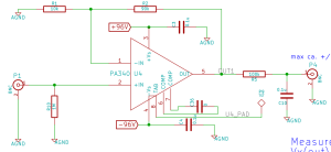
schematic_pic

See full schematic as PDF: bias_amp_v0

The high-voltage DC-rails for the op-amps are produced by connecting four +/-24 V DC-to-DC converters in series. This allows powering the amplifier from a single +12VDC powersupply-brick, and in theory produces +/-48 V for the lower-voltage op-amps and +/-96 V for the high-voltage op-amps.

One issue with DC-to-DC converters is that they produce both differential and common-mode noise on the output. Conventional filter-caps or Pi-filtering removes the differential noise but does nothing to the common-mode noise. A common mode choke and/or filtering capacitors across the isolation-barrier to the input-side ground are required to remove the common-mode noise. Here's a picture from a Murata app-note that explains the idea:
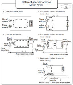
diff_common_noise

The components fit comfortably on a 100mm by 160mm PCB like this:
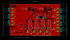
pcb_pic
Only top Cu-layer shown. Why doesn't Kicad have built-in PDF export for the PCB-editor (like in the schematic-editor)?

Gerber and Excellon files from Kicad worked without problems with CircuitCAM for producing toolpaths for BoardMaster that runs our LPKF PCB mill. The PCB after milling, rubbed with steel-wool, cleaned with isopropanol, and then coated with PRF202.
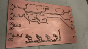
pcb_milled_bottompcb_milled_top

Components soldered, and board fit into an enclosure (Multicomp MCRECS160):
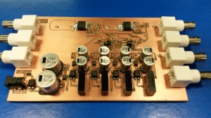
pcb_solderedpcb_boxed

When powered up the DC-rails measured slightly lower voltages than expected. I got -89V, -44V, +44V, and +89V. The no-load input current was surprisingly high at 190mA. The dc-to-dc converters have a no-load spec of 20mA, so this explains about half of the measured current. The op-amps have a quiescent current of 3.2 mA @ +/48V for OPA454 and 2.2 mA @ +/-96V for PA340. So the 'middle' DC-to-DC converters that power all four op-amps should have 2*(3.2+2.2)= 10.8mA load at 48V and the 'side' converters only 2*3.2=6.4mA at 48V. That's 17.2 mA at 48V together, which should correspond to 84 mA at 12V if we trust the 82% efficiency number from the datasheet. So we can explain 80mA as no-load current and 84 mA from the quiescent current of the op-amps. That's 164 mA together, which is about 85% of the 190mA number shown by the powersupply. If my reasoning here is way off please comment below!

Initial measurements shows that the outputs behave roughly as designed. The high-voltage outputs max out at about +/- 85 V. Note that the 10 MOhm input of a DMM measures only 99% of the actual output voltage, due to the high 100k output impedance of the amplifier.
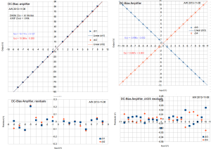
bias_amp

The frequency response is completely dominated by the 16 Hz low-pass RC-filter on the output, although the op-amps have unity-gain bandwidths of ~10 and ~2 MHz.
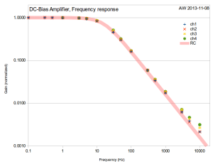
bias_amp_fresponse

Notes and comments:

  • This was the first board I designed with Kicad. It works rather well, and new enhancements are already on the way. The export of a netlist from the schematic-editor to the PCB-editor could be a bit smoother, and the footprint assignment should probably be done in the schematic-editor and the current CvPCB footprint-assignment bypassed.
  • I used quite conservative design rules(mils): clearance 16, track 25, via 55, via drl 35. This seems to work quite well. The clearance could be reduced down towards 8 mils which is the minimum isolation clearance the PCB-mill can produce. Kicad automatically enforces clearance and via design rules interactively while routing the tracks - this is probably good once you get used to it.
  • I messed up the polarity of the diode footprints - should be fixed if a second version is built.
  • Linear regulators could be added on the DC-rails, after the pi-filters. Or perhaps a shunt regulator on the high-voltage rails.
  • With no load the op-amps don't seem to heat up. So the heatsink copper areas may not be required.
  • The BNC-footprint "BNC_Socket_TYCO-AMP_LargePads_RevA" has a quite large drill-spec for the mounting holes, could be reduced from 2.2mm to 2.1 or 2.0mm. The signal pin holes are also quite close to the large mounting holes. they could be moved further away by maybe 0.5 mm.
  • I used kapton tape on the sides of the board, to insulate AGND from the aluminium case. Not sure what voltage the case should be at( +12V input ground?).
Howland constant current source

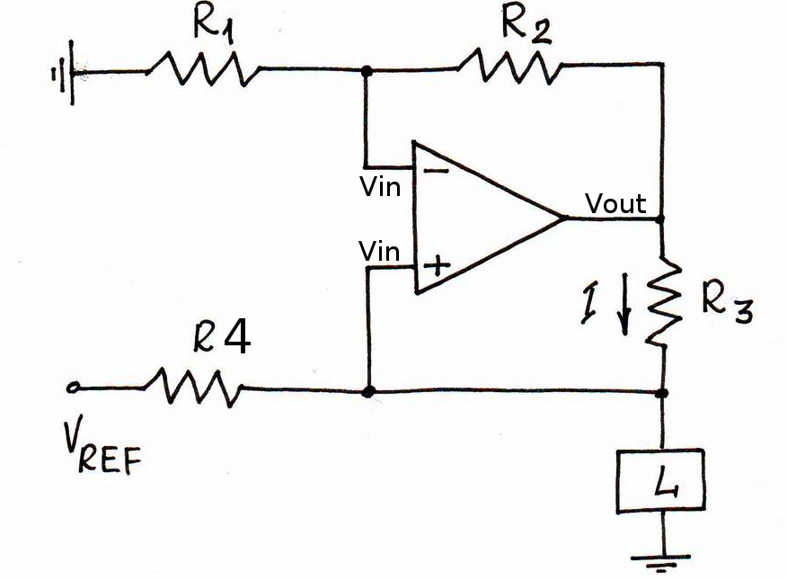
For pushing a constant 500 uA current through Pt100 temperature sensors I am using a Howland constant current source.

howland_circuit

I'm using an OP2177 op-amp. The OPA2188 would have been better, but the delivery time was too long. The four resistors come in a single 4x10k array package, and are matched to within +/-0.05 % (ACASA1002E1002P100). The reference voltage comes either from an external source, or an on-board 5V ADR425.
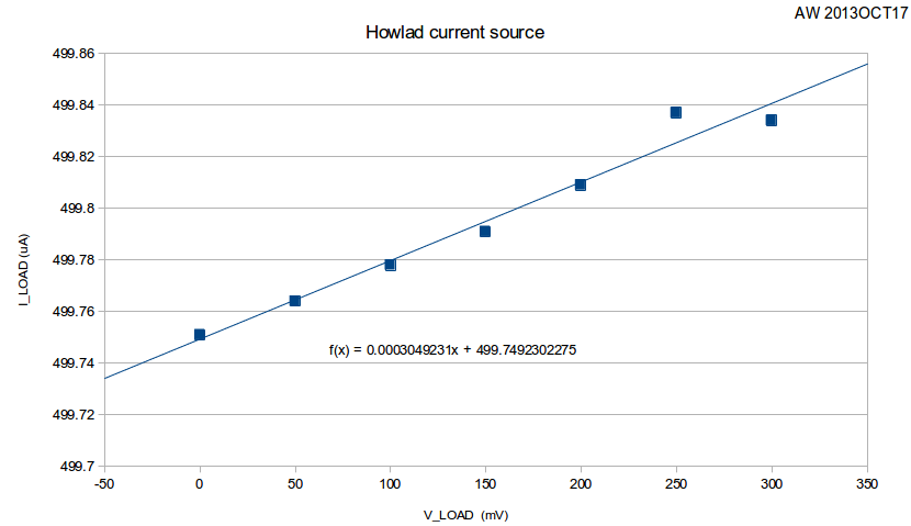
We did a test of how good the current source is, and came up with this data:

howland_data

The slope corresponds to an output impedance of 3.6 MOhms. Note that when we change the load resistance from 0 Ohms to 600 Ohms the load current changes by 83 nA, or less than 0.02% of full-scale (500uA). The 6.5-digit multimeter in the electronics lab was mostly oblivious to this change, so we used a 3458A instead 🙂

I then wanted to calculate what contribution the tolerance of the resistors R1-R4 make to the output impedance. Assuming an ideal op-amp (infinite gain, so V+ and V- at same voltage), the op-amp output voltage can be seen to be (left as an exercise for the reader):

Now we can make a monte-carlo simulation by picking values for R1-R4 with a nominal 10k resistance and an added +/-0.05% tolerance. I did this by adding a normal-distributed resistance with zero mean and 5 Ohm std-deviation.

1
2
3
4
5
6
7
R0 = 10e3
mu = 0
sigma = (0.05/100)*R0
R1 = R0 + random.gauss(mu, sigma)
R2 = R0 + random.gauss(mu, sigma)
R3 = R0 + random.gauss(mu, sigma)
R4 = R0 + random.gauss(mu, sigma)

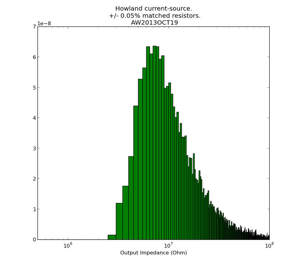
I then repeated the output impedance calculation many times, and plotted this output impedance histogram:

howland_output_impedance

It seems our measured 3.6 MOhms is slightly low, and from the resistors alone something closer to 10 MOhm should be expected. Non-ideal behaviour of the op-amp, which I haven't considered here, may also contribute. Python-script for producing the histogram: howland_calc.py

See also: AN-1515 A Comprehensive Study of the Howland Current Pump (up to 1 MOhm output-impedance with 1% resistors is mentioned)

This current-source is part of the Pt100 frontend.

Agilent 34901A and 34907A breakout boards

Update 2015-09-16:  Csaba Toth sent a picture of his front-panel for these breakout boards. Very nice finish with text/graphics on the 19" rack panel!

20150908_231719

Front

Update 2015-05-15: Files for PCB manufacturing: top, bottom, outline Gerber files, and Excellon drill files.

When opened with e.g. gerberview they should look like this:

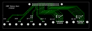
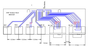
breakout2 breakoutThe connector placement is shown here (sorry I don't have a drawing for the one with 20 BNC connectors):

breakout2_connectors

A frustratingly large portion of any electronics or control system build has to do with cables and connectors. So here we go...

I'm using an Agilent 34970A datalogger/switch, which is a 6.5 digit (~22 bit) multimeter that takes up to three plug-in modules with various functions.
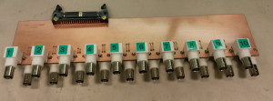
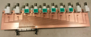
I'm using one 34901A module for 20 channels of DC voltage inputs. On the module there are 40 screw-terminals for these voltages which I have connected to a 40-pin ribbon cable that connects to this breakout board with 20 BNC connectors. Our PCB-mill can do 300mm long PCBs, which is just long enough for this board if the BNC connectors are interleaved on different sides of the board. Mounting BNC-connectors right next to each other on the same side is bad idea anyway as the connectors on the cables will not fit that closely. It should be possible to mount the whole thing in a 1U 19" rack panel.

34901A_breakout_top_2013sep 34901A_breakout_bottom_2013sep

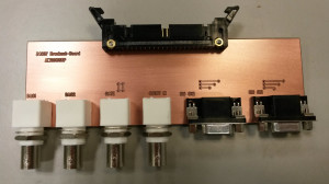
For controlling the TEC drive I need analog outputs, provided by a 34907A module. Again I'm using a 40-pin ribbon cable from the screw-terminals on the module, and the breakout board has four BNC connectors: Two DAC outputs, one counter input, and a gate input for the counter). Additionally there are two 8-bit digital I/O ports which are routed to two DB9 connectors on the breakout board.

34907A_breakout_top_2013sep