TEC Drive in enclosure

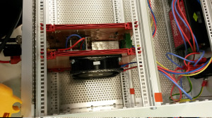
The TEC drive I have been working on is now mounted as a plug-in card in a 3U 19" rack enclosure like this:

tec_drive_rack_mounted

The card next to the TEC drive holds an 80 mm fan which helps cool the heatsinked linear regulators and the linear H-bridge that drives the TEC.

tec_drive_rack_backpanel

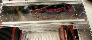
The back of the 19" rack enclosure holds two TRACO POWER PSUs that produce +/-5 V at max 4 A and +/-15 V at max 667 mA. An IEC power-entry module containing the IEC-connector, a fuse, and a power switch is visible far right. Far left is a small PCB for distributing +/-15 V to other cards in the same enclosure.

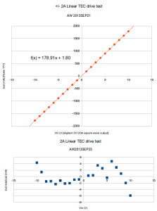
Added cooling allows testing the drive at the max input level of +/-10 V, which should produce (roughly) an output of +/-2 A.

tec_drive_test_2013sep23

The output current follows 179 mA/V * Vin + 1.8 mA with a maximum nonlinearity of about 6 mA (0.3% of full-scale). Despite the fan-cooling the transistors still get quite hot and staying below 1 A output in continuous operation is probably a good idea.

TEC-Drive heat sinks

tec-drive_heatsinks_2013sep4

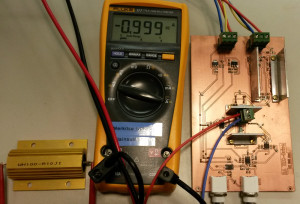
I made four heat sinks from aluminium L-profile for the linear TEC drive. Two 30 mm long for each side of the H-bridge (middle), and two 50 mm long for the voltage regulators(top right).

The regulators take 5 V input and produce 2 V, so they each dissipate 3V *ITEC Watts. The H-bridge dissipation is load-dependent, but for a low resistance load the dissipation is almost 2V*ITEC Watts. Here I am using a resistor (lower left) as a dummy load.

I tested the drive at 1 A for a few minutes, and the heat sinks do get quite warm. For continuous use at 2 A I think a fan will be required.

TEC-Drive prototype

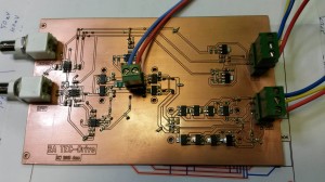
I've been assembling and testing this PCB over the past few days:

tec-drive_prototype_2013_08_01

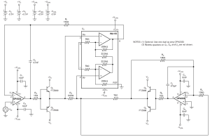
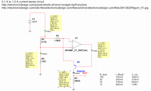
It's a linear +/-2 A voltage-to-current amplifier meant for driving a constant current through a Thermoelectric Cooler (TEC). The circuit is (loosely) based on a 2001 Burr-Brown/TI application note "SBEA001 - Optoelectronics Circuit Collection".

sbea001_tec-drive_v3

Description: U1 drives one half of the H-bridge (Q1 and Q3) based on a feedback signal which is the amplified (U3) voltage drop across a current-sensing resistor (R4). The other H-bridge half (Q2 and Q4) is driven by an inverting amplifier (U2) which forces the other end of the TEC symmetrically, inverted, to follow the output from U1.

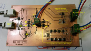
Here's how these things look on the PCB:

tecdrive_drawing

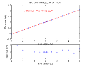
After some assembly, bugfixing, and tweaking I measured a DC transfer function like this:

tec-current_vs_input_voltage_2013aug1

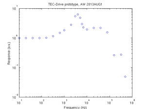
I am happy with the small offset of <0.2 mA and the linearity seems good. There is a rather large gain-error since the design-goal was 200 mA/V and the measured sensitivity is 179 mA/V. The AC frequency response is quite ugly with a high peak at a few kHz. In the time-domain this shows up as severe ringing when driven by a square-wave input. (aside: the SBEA001 application note shows a SPICE-simulated frequency response up to MHz frequencies - theory/simulation and practice differ a lot in this case!).

tec-drive_f-response_2013aug1

Things learned so far:

  • The original design used OPA353 op-amps. I had assumed these will work with bipolar +/-12 V supplies and the output swing would be close to +/-10 V. Not so! (the OPA353 is a single-supply op-amp). I used TL071 op-amps instead and they seem to work.
  • Bypass capacitors close to the collectors of Q1-Q4 are essential (but not shown in the circuit-diagram!). The feedback loop would go mad with oscillations without 1 uF caps placed close to Q1-Q4.
  • Q1-Q4 (and the linear regulators) will require heatsinking for >1 A currents.
  • The current-sensing instrumentation amplifier U3 (I used an AD8221 instead of the INA155 in the application note) is probably the most sensitive part of this circuit. I added 200 Ohm series resistors on the inputs, as well as low-pass filter capacitors (100 nF) to ground on both + and - inputs. This seems to have a calming effect on noise/oscillation of the feedback loop.
  • This kind of push-pull power stage shows significant cross-over distortion when the input signal crosses zero. Here the op-amp that drives the bases of the transistors needs to slew quickly either up or down in order to turn off one transistor and turn on the other one.

If all goes well this TEC-drive will be part of a temperature control system consisting of about five different PCBs or circuits:

  • Digital controller. Talks over SPI to DAC and ADC cards. Runs PID and/or feed-forward algorithm on real-time OS to keep temperature steady.
  • ADC-Card. Reads +/-10 V input voltage at 24-bit resolution and 1-100 samples/s speed.
  • DAC-Card. Outputs +/-10 V voltages as input to TEC-drive. 1 sample/s speed is sufficient.
  • Temperature-sensor frontend. Converts pt100 (or alternatively 10k NTC) resistance change into +/-10 V output for ADC. Previous blog posts here and here.
  • TEC-Drive (this PCB). Converts +/-10 V input from DAC into a +/-2 A constant current through the TEC.

pt100 frontend - v2

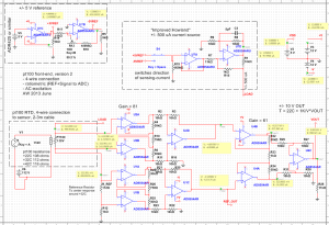
Here is version two of a precision pt100 frontend for temperature measurements between +22C and +42C. The circuit uses a 4-wire connection with a +/-500uA sensing-current. It outputs a +/-10V voltage centered around +32C by way of a 112 Ohm reference resistor. The voltage over the reference-resistor can be used to correct for drift in the sensing-current.

Compared to v1 I changed the current source to the "Improved Howland" design, and assembled the instrumentation amplifiers from zero-drift op-amps with very small input offset voltage and input bias current.

Note: The op-amp shown, AD8551/8552/8554, is a single-supply +5V op-amp and this circuit will not work as such (NI Multisim will happily simulate it though!). Use e.g. OP2177 or OPA2188 for bipolar operation at +/-12 V.

pt100_piiri

pt100 frontend

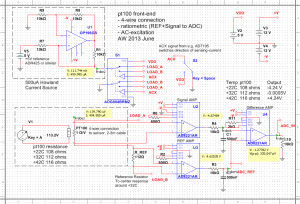
Here's a sketch for a pt100/RTD frontend circuit.

pt100_frontend_2013june11

There are a couple of ideas here which should improve precision:

  • 4-wire connection, to eliminate lead-resistance effects
  • Ratiometric measurement (both a reference and the signal go to the ADC). This should minimize effects from fluctuations in the sensing current.
  • AC-excitation. The sensing current can be reversed with at TTL logic signal. Some ADC chips have an output for this, and they average the measurement done with current flowing in both directions. This eliminates effects from DC-offsets (thermovoltages etc).
  • The circuit is centered around a particular temperature (here +32C) and the signals amplified so a twenty degree span of +22C to +42C should give about +/- 4 V output.

NI Multisim file for this: pt100_sensor_circuit_v3

TEC mount for laser-module

tec_adapter_1

tec_adapter_2

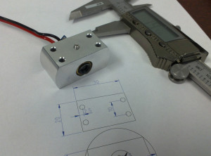
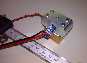
I made this aluminium bit on the lathe/mill today. It holds a blue laser-module from dealextreme. The brass barrel measured about 11.81 to 11.84 mm in diameter so I first drilled a 10mm hole, then opened it up slowly on the lathe until the module just fit the hole. There is an M3 set-screw to hold the laser module in place. Four long M2.5 screws clamp the aluminium part into contact with a peltier-element and the copper heatsink. A thermistor for temperature measurement and feedback control will be glued to the aluminium part as close as possible to the peltier.

Temperature control of the laser diode should provide for rough tuning of the laser wavelength. We want the wavelength to be about 405.2 nm, to be used for photoionization of Strontium.

Aside: A few years ago I tried to order some of these 405nm laser-pointers to the university. It was impossibly difficult because the shipments were stopped by the customs. Negotiations with the radiation-safety authorities did not help. It's simply forbidden to import non CE-approved laser-pointers - it doesn't matter if you are a researcher or work at a research institution. The story is completely different for laser modules (this is exactly the same product as the laser-pointer, but without the pen-like shape and the battery holder). Apparently these are classified just as "diodes" or "electronic components" and there are no problems getting them through customs.

PD-Amps compared

pd_amp_1 pd_amp_v2

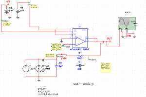
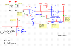
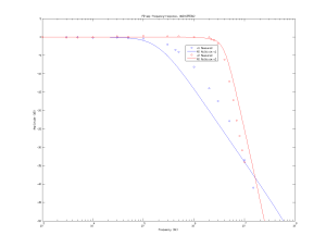
The first design is a single transimpedance-amplifier (TIA) using an ADA4817 and a 1 MOhm resistor. This isn't a great design, since the op-amp is much too fast compared to what is needed/required here. The second design is a 7 kOhm TIA (AD8597) followed by a ~140 V/V gain non-inverting amp (ADA4817). This gives the same total effective gain of ~1 MOhm.

These circuits were designed for a 2 V output with a 2 uA photocurrent produced by about 5 uW of HeNe laser light at 633 nm. The output will hit the "roof" (the positive rail) at about 12 uW of optical power.

The agreement between simulation and experiment is not very good. I suspect my extremely simple LED-test is to blame. I should build a VCSEL circuit which allows testing these and other photodiode receivers to much higher frequencies.

pd_amp_comparison


PD-Amp v.2 assembled and tested

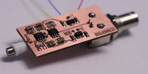
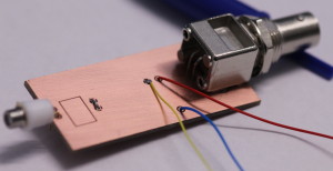
pd_amp_smd-side_2013feb11 pd_amp_thruhole-side_2013feb11

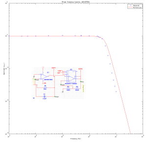
I assembled and tested the latest photodiode-amp today. I tested the frequency response using a red LED driven directly by an Agilent function-generator with an offset of 1.2 V and a 600 mVpp sine-wave. The LED datasheet doesn't specify a rise-time or bandwidth, but I'm hoping it is fast enough to test this 2-3 MHz receiver. I do have some small VCSELs that should be very fast and suitable for testing photodiode receivers up to 500 MHz and beyond.

The signal from the LED caused a 3 V output swing, which explains the slightly lower observed (large-signal) bandwidth compared to the simulated (small-signal) bandwidth. Some of the difference between the simulated frequency-response and the measured one is probably explained by stray capacitance which slightly lowers the bandwidth.

pd_amp_f-response_2013feb11_withcircuit_x


Photodiode amplifier - version 2

A revised version of the circuit and PCB for a photodiode amplifier, to be used in PDH-locking (Pound-Drever-Hall) as well as RAM-nulling (residual amplitude modulation) in a laser experiment I am doing. The changes compared to the first prototype are:

  • The required bandwidth and gain is not easy to achieve in one stage, so there's a second stage of amplification after the transimpedance amplifier.
  • I'm suspicious of the noise caused by the switched-mode powersupply, as well as the DC2DC converter, of the previous design. So this circuit has just +/-5 V regulators and can be driven from a regular (known good) +/-12 V lab powersupply (or even two 9 V batteries).

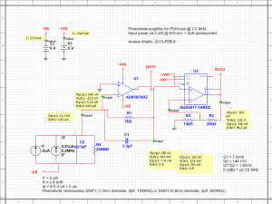
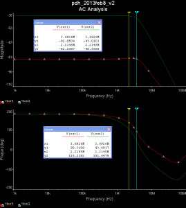
Here is a schematic and simulation results produced with the free version of NI Multisim from Analog Devices. The design is for roughly 1 MOhm of transimpedance gain in total, here split between 7 kV/A transimpedance gain, and 144 V/V for the non-inverting second op-amp. At 1 kV/A of transimpedance gain a 5 uW optical signal at 633 nm (HeNe laser!) that produces a 2 uA photocurrent will result in a 2 V output signal. The AC analysis shows very slight gain-peaking for the transimpedance-stage (red trace) and a -3 dB bandwidth of >3 MHz overall (green trace).
pd_amp_2013feb8 pd_amp_2013feb8_ac_sim

The first op-amp used in the transimpedance stage only needs to have a bandwidth slightly exceeding the transimpedance gain bandwidth (the feedback resistor R1 together with the compensating cap C1, the capacitance of the photodiode C2, and the input-capacitance (not shown) of the op-amp form an RC low-pass filter). The AD8597 is marketed as "ultralow distortion/noise" and is fast enough (10 MHz). The second non-inverting op-amp needs a high gain-bandwidth-product (GBP) since we are amplifying ~100-fold here. The ADA4817 has a small-signal bandwidth of 1 GHz and GBP~400 MHz, so should work OK here.

A voltage of only 14 mV over the transimpedance-resistor is not ideal. The Johnson noise (which in principle a good designer can control/minimize) in the resistor will dominate over the shot noise (which we cannot avoid) in the optical signal. For shot-noise limited performance the rule of thumb is to make the voltage drop at least 51 mV (which will make Johnson and shot noise equal). Without tricks however that is not possible as here we have both a weak signal (2 uA of photocurrent), we want a high gain (1 kV/A in total), and we want to go fast (~3 MHz bandwidth)! If you relax any of those requirements (more power, less gain, slower response) it is straightforward to build a shot-noise limited amplifier in one or two stages.

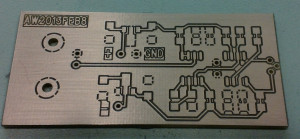
The PCB, fresh from the mill:
pd_amp_pcb_2013feb8

Far right is a 3-pin TO-18 socket for the photodiode. Right-middle are the two op-amps with their feedback-resistors/caps, as well as two de-coupling caps for both +5V and -5V. Left-middle are 7805 and 7905 voltage regulators, and the BNC output-connector is far left. All the surface mount components are mounted on the top layer of the board, while the through-hole components are bottom-mounted. Resistors and caps are 1206-size. This PCB should fit the earlier enclosures I turned on the lathe.

Hopefully I will have time to assemble and test one or two of these next week. I should measure the actual frequency-response and compare it with the simulated one.