Meinberg Lantime M300

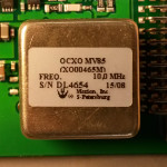
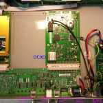
Following Dave's advice here: "Don't turn it on - take it apart!"

Meinberg Lantime M300 - Multi Reference NTP server. This server works as stratum-1 using a number of different input signals such as GPS, 1PPS, 10MHz, and IRIG/Timecode.

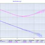
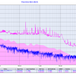
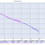
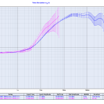
The loop time-constants seem to be very long, since the ADEV plot does not change much (at least not immediately) when connecting or disconnecting e.g. the 1PPS or 10MHz inputs. If I would be more patient I would measure it free-running and with all the different stratum-1 input signals for a few days each - that would maybe show some interesting things about how the internal OCXO is locked to the reference inputs. My assumption would be that IRIG would produce the worst ADEV, GPS second worst, 1PPS quite good, and the 10MHz input should produce an excellent ADEV with the shortest lock time-constant.

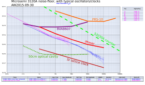
Microsemi/Symmetricom 3120A noise floor

This was measured by taking a H-maser 10MHz signal (output from a frequency distribution amplifier) and splitting it in two for the 3120A REF and DUT channels with a ZFSC-2-1+ passive splitter.

The first measurement is with 50 Hz bandwidth and a duration of 5 minutes. The second measurement is at 5 Hz bandwidth and ran overnight for 12 hours.

Here's the ADEV plot with some typical performance-curves added.

floor_with_comments

Data from:

SRS FS710 noise measurement

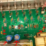
Update: changing the main electrolytic capacitors as well as the tantalum caps around the 7805/7905 voltage regulators did not help. There is still about 600 mVpp of ripple on the +/- 13.9 VDC inputs to the regulators.

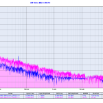
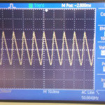
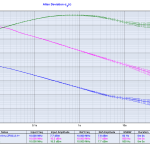
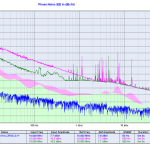
Here's a noise measurement on an old second-hand SRS FS710 distribution amplifier. I wonder if the excessive noise at 50 Hz and harmonics is within spec or a result of old age?

Measurement setup: 10MHz signal to a Mini-Circuits ZFSC-2-1+ splitter, one branch to 3120A REF-input, the other branch to the FS710 input, and FS710 output1 to the 3120A DUT input. Noise floor was measured with the same setup but bypassing the FS710.

White Rabbit Switch noise measurement

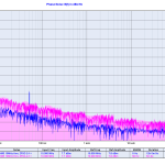
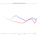
I measured the CLK2 10 MHz RF-output of two White Rabbit switches with a Microsemi 3120A. The results are similar to previous results with ADEV(1s)=1.5e-11.

When phase-locked to an external reference clock the long-term stability is obviously much better than when free-running, but for small tau, or high offset-frequency in the phase noise plot, the free running oscillator is actually better.

CONT vs RCON mode on the 53230A frequency counter

This is a follow-up to my earlier notes on the 53230A noise floor.

Naively I did the initial frequency-counting tests using READ?, which is wrong both because it produces data with dead-time and because the consensus for what is meant by Allan deviation assumes pi-counting.

Driven by marketing, no doubt, the 53230A employs internal averaging (something akin to lambda-counting) both with the simple READ? command and the continuous CONT mode mentioned in the manual. Amazingly you have to use the undocumented RCON mode to get pi-counting which will produce correct Allan deviations.

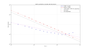
Here is a plot. The opportunity for making errors (with pi- vs. lamda-counting, and gap-free data) is less in time-interval mode, and I have indicated the 12 ps RMS noise floor (1.8e-11/tau in terms of Allan deviation) with a black dashed line. In RCON mode the noise floor has the same 1/tau dependence and I get about 3e-11/tau. If however you simply use the built-in settings of the counter with READ? or CONT you get a noise floor of about 2e-12/sqrt(tau) due to the internal averaging going on behind the scenes.

RCON_vs_CONT

For a paper that explains pi- and lambda-counting see Dawkins2007 (fulltext PDF on ReaserchGate). Enrico Rubiola also has notes on counters.

Datafiles and script for ADEV and figure: 2015-06-18_rcon_cont.zip

Clock display with Python and Tkinter

On github: https://github.com/aewallin/digiclock

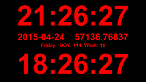
clock_display_2015-04-24

A simple clock display with local time, UTC, date (iso8601 format of course!), MJD, day-of-year, and week number. Useful as a permanent info-display in the lab - just make sure your machines are synced with NTP.

1
2
3
4
5
6
7
8
9
10
11
12
13
14
15
16
17
18
19
20
21
22
23
24
25
26
27
28
29
30
31
32
33
34
35
36
37
38
39
40
41
42
43
44
45
46
47
48
49
50
51
52
53
# use Tkinter to show a digital clock
# tested with Python24    vegaseat    10sep2006
# https://www.daniweb.com/software-development/python/code/216785/tkinter-digital-clock-python
# http://en.sharejs.com/python/19617
 
# AW2015-04-24
# added: UTC, localtime, date, MJD, DOY, week 
from Tkinter import *
import time
import jdutil # https://gist.github.com/jiffyclub/1294443
 
root = Tk()
root.attributes("-fullscreen", True) 
# this should make Esc exit fullscrreen, but doesn't seem to work..
#root.bind('',root.attributes("-fullscreen", False))
root.configure(background='black')
 
#root.geometry("1280x1024") # set explicitly window size
time1 = ''
clock_lt = Label(root, font=('arial', 230, 'bold'), fg='red',bg='black')
clock_lt.pack()
 
date_iso = Label(root, font=('arial', 75, 'bold'), fg='red',bg='black')
date_iso.pack()
 
date_etc = Label(root, font=('arial', 40, 'bold'), fg='red',bg='black')
date_etc.pack()
 
clock_utc = Label(root, font=('arial', 230, 'bold'),fg='red', bg='black')
clock_utc.pack()
 
def tick():
    global time1
    time2 = time.strftime('%H:%M:%S') # local
    time_utc = time.strftime('%H:%M:%S', time.gmtime()) # utc
    # MJD
    date_iso_txt = time.strftime('%Y-%m-%d') + "    %.5f" % jdutil.mjd_now()
    # day, DOY, week
    date_etc_txt = "%s   DOY: %s  Week: %s" % (time.strftime('%A'), time.strftime('%j'), time.strftime('%W'))
 
    if time2 != time1: # if time string has changed, update it
        time1 = time2
        clock_lt.config(text=time2)
        clock_utc.config(text=time_utc)
        date_iso.config(text=date_iso_txt)
        date_etc.config(text=date_etc_txt)
    # calls itself every 200 milliseconds
    # to update the time display as needed
    # could use >200 ms, but display gets jerky
    clock_lt.after(20, tick)
 
tick()
root.mainloop()

This uses two small additions to jdutil:

1
2
3
4
5
6
7
def mjd_now():
    t = dt.datetime.utcnow()
    return dt_to_mjd(t)
 
def dt_to_mjd(dt):
    jd = datetime_to_jd(dt)
    return jd_to_mjd(jd)

Keysight 53230A noise floor test

We got a new 53230A counter to the lab, so I decided to run some basic tests on it.

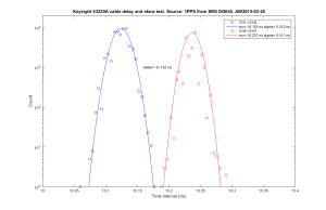
I collected time interval data using a 1-PPS source (H-maser through a SRS DG645), and wired this with a T-connector from CH1 to CH2 with a ~1 m (10 ns delay) cable. This should show the noise floor for time interval measurements as well as CH1/CH2 timing skew when measured the other way around (i.e. from CH2 to CH1). The 10 MHz external reference (at the back) was connected to a H-maser.

53230A_PPS_skew
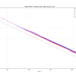
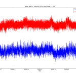
The results show standard deviations of 12 ps (CH1->CH2) and 11 ps (CH2->CH1) respecively, with a channel skew of 112 ps. Compare to the single-shot spec of sqrt(2)*20 ps = 28 ps and Agilent/Keysight's marketing video on youtube.

I also collected 10 MHz frequency counter readings on CH1 (source: H-maser) with gate times of 0.1 s, 1.0 s, and 10.0 s. I collected the data with a simple program that just calls the "READ?" function repeatedly, which does result in some dead-time between measurements.

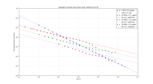
Here are the results in terms of Allan deviation. I used allantools.

Keysight_53230A_noise_floor

The time interval noise floor looks like white phase noise with an Allan deviation of 1.8e-11/tau. This is consistent with the 12 ps RMS value found above. It is left as an exercise for the reader to show that ADEV(1s) = sqrt(3)*RMS-time-interval-noise (correct??).

The frequency counting noise floor depends on the gate time, and I get 5e-12/sqrt(tau), 2e-12/sqrt(tau), and 6e-13/sqrt(tau) for gate times of 0.1 s, 1.0 s, and 10.0 s, respectively. This looks like white frequency noise. Enrico Rubiola has notes on frequency counters that may explain the numbers.

White Rabbit Switch PPS-output test

We got some White Rabbit Switches and I did an initial test of the pulse-per-second (PPS) output stability. In contrast to earlier measurements that showed 200ps or so of white phase noise, the PPS output on the WRS now seems a lot more stable. For various reasons the noise-floor (red data) of our 53230A time-interval-counter is at around 50e-12 @ 1s, and the WRS PPS output is at very much the same level of stability. Another 53230A counter shows about 13 ps standard-deviation for a cable-delay measurement - so I may redo these measurements with that counter. In any case a real evaluation of the short-term stability requires a DMTD measurement at 10 MHz.

53230A counter input channel fix

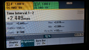
Update: after the fix the counter seems OK again. 12 ps standard deviation (61k PPS-pulses, collected over 17 hours) on a cable-delay test:
54230A_cable-delay

53230A_fix

A broken CH1 input trace seems to be a common problem on the Agilent/Keysight 53230A counter. This is the second unit with the same problem we have seen.

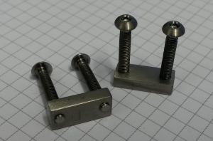
The fix is to bypass the broken trace with a wire directly from the center of the input-BNC to the next unpopulated SMD-pad.