White Rabbit Fine-Delay time-stamp testing

I'm testing the White Rabbit Fine-Delay FMC. It has an ACAM TDC-GXP time-to-digital converter that time-stamps the leading edge of an input trigger signal with ~30 ps resolution.

Recent work by Alessandro Rubini introduced a raw_tdc=1 driver mode which on my computer is able to collect time-stamps at a maximum rate of ca 150 kHz. Each time-stamp is 24-bytes, so this corresponds to a data-stream of roughly 4 Mb/s.

The video shows two graphs that update in real-time on the machine that collects time-stamps. The first is simply a (reciprocal) frequency counter where we count how many time-stamps arrive within a certain gate/window.

The second part of the video shows a modulo(tau) histogram where we bin time-stamps modulo tau into a histogram. The histogram was calculated for tau=100 us and an input frequency of 1 kHz was used. This results in the central peak in the histogram. I then slightly increased the frequency to 1.000010 kHz which makes the peak wander to the right. The peak on the right was produced by again tuning the input frequency to exactly 1 kHz. Similarly a lower input frequency of 999.970 Hz makes the peak wander to the left, and the peak around 20us was produced after tuning back to 1 kHz.

This hardware/software combination will be useful for collecting statistics and correlations in any experiments where a pulse type detector is used to measure something - provided the pulse-rate is below 150 kHz or so.
Pulse Stretcher - v1

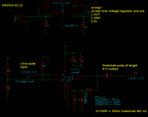
A first try at this pulse stretcher circuit based on the LT1711 comparator. I need it for stretching a short 10ns pulse from a PMT.

stretcher_sch_2014-02-13

The idea is to use the output latch of the LT1711. Once the output goes high, the combination C4 R4 keeps the latch pin (and thus the output) high for a time R*C. The Schottky diode is there to prevent the latch pin from swinging to far negative once the output goes low.

stretcher_pcb_2014-02-13

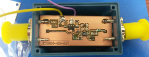
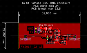
The PCB is made to fit into a BNC-BNC enclosure such as the ones from Pomona.

pulse_stretcher_prototype

Messing up the pin-order of voltage regulators is becoming a habit! Note how the regulator is mounted the wrong way round compared to the PCB design - because I had the pin order wrong in my schematic.

pulse_stretcher_input_output

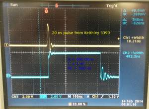
I used a Keithley 50 MHz function generator to generate a 20ns long input pulse (the shortest possible from the Keithley) and the pulse-stretcher outputs a ca 483 ns output pulse. The prototype used a 1 nF capacitor with a 500 Ohm resistor which gives a nominal time-constant of 500 ns. The output pulse duration is far from constant and varies quite a bit from pulse to pulse.

pulse_stretcher_propagation_delay

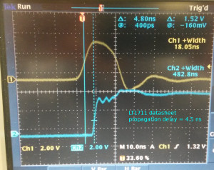
This verifies that the propagation delay of the LT1711 in this circuit is within specifications, ca 4.5 ns. In addition to the comparator there is also maybe 70 mm of BNC-connectors, wires, and PCB-traces in the signal path, but that would add only ~350 ps to the propagation delay (assuming 2e8 m/s signal velocity).

One problem with this design is that it is sensitive to the load impedance connected to the output. With a 1 MOhm setting on the oscilloscope the pulse-length is correct, but switching to a 50 Ohm load impedance allows the capacitor to discharge significantly through the load impedance.

Version 2 of this circuit should thus add an output buffer (fast, low-jitter!) that can drive both 1 MOhm and 50 Ohm loads. An adjustable trigger level for the -Input of the LT1711 comparator could also be useful.

allantools

Python code for calculating Allan deviation and related statistics: https://github.com/aewallin/allantools

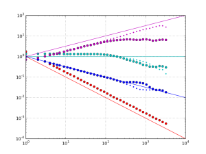
Sample output:
allantools_output

Cheat-sheet (see http://en.wikipedia.org/wiki/Colors_of_noise).

Phase PSD Frequency PSD ADEV
1/f^4, "Black?" 1/f^2, Brownian, random walk sqrt(tau)
1/f^3 ?, "Black?" 1/f Pink constant
1/f^2, Brownian, random walk f^0, White 1/sqrt(tau)
f^0, White f^2 Violet 1/tau

Phase PSD is frequency dependence of the the power-spectral-density of the phase noise.
Frequency PSD is the frequency dependence of the power-spectral-density of the frequency noise.
ADEV is the tau-dependence of the Allan deviation.

These can get confusing! Please comment below if I made an error!

White Rabbit DIO vs. FDELAY PPS output test

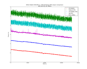
I ran a test to compare the quality of PPS outputs from a DIO (used as GM) and an FDELAY (used as slave) White Rabbit SPEC/FMC combinations. Here is the phase data measured with a Time-interval-counter. The nice clean traces are derived from a H-maser. We then lock a BVA (internally 2x multiplied to 10MHz) to this PPS signal. The GM node is locked to this 10MHz signal.

The average of each trace was removed, and the traces are offset for clarity.

fdelay_gm_pps_time-series_2014-01-29

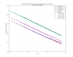
The Allan deviations look like this. Both the DIO and FDELAY PPS outputs have allan deviations about 5x worse than the BVA used as input clock for the GM.

fdelay_gm_pps_ADEV_2014-01-29

AD9912 DDS Test

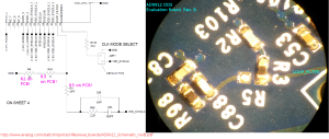
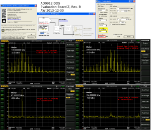
Update: it turns out the PLL filter components were not connected at all during the first tests I did 🙂 Here's a picture that compares the schematic against the actual board. When I changed the 0R resistor from position "R3" to position "R5"  the PLL started behaving much more nicely. If anyone from AD is reading - please update your documentation!

ad9912_eval_board_pll_schematic

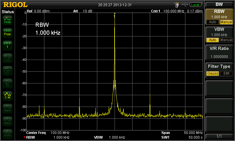
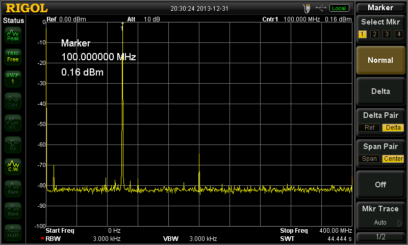
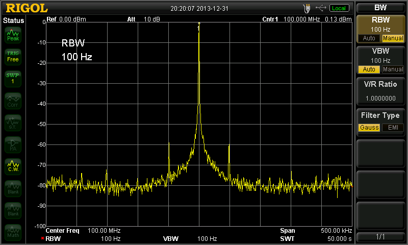
With this change, and a 66x PLL multiplier giving a 10MHz x 66 = 660 MHz SYSCLOCK I get quite nice output:

Fout100M_Span50M Fout100M_Span400M Fout100M_Span500k

The output is set to 100 MHz and has an amplitude of ~0 dBm. There are -60 dBm spurs at +/- 50 kHz (not sure why?), -70 dBm spurs at +/- 10MHz, and a -65 dBm second harmonic at 200 MHz.

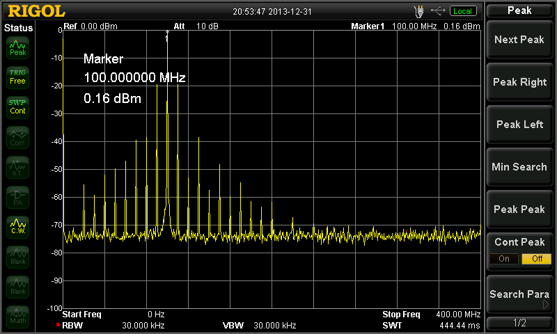
If I activate the "2x Reference" setting which detects both rising and falling edges of the input clock, and use that with a 40x PLL for a 10MHz x2 x40 = 800 MHz SYSCLOCK I still get very strong spurs at 10 MHz:

Fout100M_Span400_PLL_2x40x

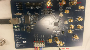
I have been testing this AD9912 DDS evaluation board:
ad9912_evkit_pcb_text

So far the results are a bit strange, with output as advertized only when no external input clock is supplied. Strange.

dds_test_2013-12-30

Comparing GPS PPP solutions

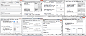
Update3 on 2014-02-20: by popular demand, screenshots of options (at least roughly correct...) used in RTKPOST to get the results shown:

rtklib_settings_2014-02-20

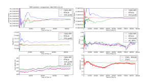
Update2: gLAB data now at 30s intervals, and an error-plot that compares CSRS to gLAB clock offset.

ppp_2013-12-25_glab


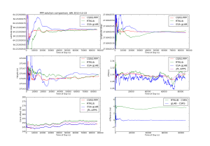
Update: using the latest RTKLib from github on Ubuntu, I now got this, with the lat/lon/height results between CSRS-PPP and RTKLib in better agreement. There is still a 4ns offset between the clock results - which curiously is about 0.5*ZTD, but this may be just a coincidence.

ppp_2013-12-25

GPS based Precise Point Positioning is used worldwide to compare clocks against each other and maintain UTC.

The idea is to connect your clock to a dual-frequency GPS receiver that collects data (in RINEX format). The RINEX data is then post-processed by using satellite orbit and clock information available (with delay) from the IGS. While normal GPS has a precision of maybe 1-10 meters (~10 ns clock offset/noise), PPP can achieve <1 cm precision (<1 ns clock offset).

I tested a few of the PPP algorithms I found by running them on the same datafile (KAJA2900.13O) and got the results shown below.

If anyone wants to try this at home you will need from the IGS (I used RTKGet, a tool that comes with RTKLib to download these): clock data CLK file igs17624.clk, orbit data SP3 file igs17624.sp3, NAV file brdc2900.13n, antenna correction ANTEX file igs08.atx, earth rotation parameters ERP file igs17627.erp, and possibly also an ocean tide loading BLQ file available from Onsala Space Observatory.

ppp_solutions_2

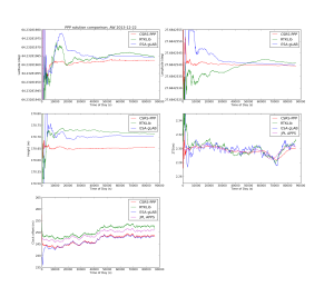
The CSRS-PPP and ESA-gLAB clock offset solutions agree reasonably well, but the clock offset of the RTKLib/JPL-APPS solutions differ by  3-4 nanoseconds - which is a lot if we are using this for monitoring/steering an atomic clock. I'm not sure why this happens - if anyone knows how to reproduce the CSRS-PPP results with RTKLib please let me know!

  • CSRS-PPP is an online web-based tool that returns results by e-mail. AFAIK the same code is used by the BIPM to maintain UTC.
  • JPL-APPS is a similar web-service by NASA.
  • ESA gLAB and RTKLib are open-source software packages for GPS/GNSS processing.

See also: A Comparison of Free GPS Online Post-Processing Services


Strontium ion(s) trapped!


A major milestone towards the ion clock was reached today: we trapped the first Strontium ions!

This involves first heating a dispenser that contains Strontium atoms with about 4-5 W (4 A and 1 V). The atoms that fly out of the dispenser are then photoionized using two blue lasers, one at 461 nm and another at 405 nm (we use a laser from a blue-ray drive for this!). We now have Sr+ ions that can be trapped in a Paul trap. A high-voltage (300 Vpp) ~10 MHz sine-wave is applied to the electrodes of the trap. Another blue laser at 422 nm is then used both for laser-cooling and as a means to detect the ion. What we see in the video is the ion fluorescence at 422 nm when it jumps down to the ground state from an excited state. The excited state can also decay into a dark state and we need a re-pump laser at 1092 nm to keep the ion in the Doppler cooling cycle. The fluorescence emitted from one or a few ions is very weak, and we used an image-intensifier and a CCD camera with 500 ms to 1 s exposure time for this video.

The camera software produces FITS frames as output. I used these commands to make the video:

mogrify -format png *.fts   # convert to PNG
mogrify -crop "640x480+436+315"  +repage *.png  # crop to the interesting area
mogrify -contrast-stretch 10x100 *.png # improve contrast
ffmpeg -r 3 -f image2 -i 'myframes_%02d.png' -qscale 1 'video.avi'

On the last line "3" is the desired frame-rate of the output. I then concatenated a few of these videos together with

mencoder video1.avi video2.avi  -mf fps=3 -oac copy -of lavf  -ovc copy 
-lavcopts aglobal=1:vglobal=1:coder=0:vcodec=mpeg4:vbitrate=4500 -vf scale=1280:720  -o output2.mp4

Strontium 461nm absorption/fluorescence revisited

This is the same experiment we did back in April, but now "in-situ" in another vacuum system that houses our RF endcap trap. The thin ray of light that slowly switches on and off is a 461nm blue laser-beam that excites Strontium atoms that fly in from the lower right corner of the picture. The on/off switching happens because we slowly scan the laser frequency back and forth and as a result different parts of the atom-stream absorb and emit.

Next stop: ionizing the atoms and trapping a single ion in the RF trap.

See also:

NTP shared-memory refclock driver for White Rabbit SPEC

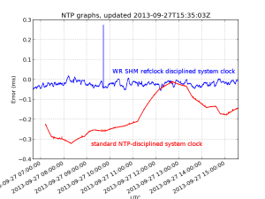
ntp_graph

I've been playing with White Rabbit hardware at work. White Rabbit uses a combination of SyncE and PTP to perform very precise (<1 ns) time-distribution.

The standard low-precision way to distribute time is NTP. I hacked together a very experimental "Type 28" NTP refclock driver that reads the WR-time from SPEC shared memory and writes it to another location in shared memory where NTP expects it. Code over here: https://github.com/aewallin/ptp2ntpd

The graph shows system clock variations compared to WR-time (which we assume is very accurate) for a computer with the WR-refclock driver enabled (blue trace, minpoll 16 s), and another computer where the system clock is kept on time using standard NTP (I just added some servers to ntpd.conf, no other settings changed from default Ubuntu 12.04LTS). The WR-disciplined clock stays within maybe 50 microseconds with no net drift during the ~9 hour measurement, but the trace is quite jumpy. The NTP-disciplined clock wanders around much more (300 us) but the trace is smoother.

NTP time measurement

NTP_time_2013jul26

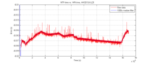
Here's a plot of the time error between the standard unix system-time, kept on time using NTP, and a much more accurate PTP-server based on White Rabbit that runs on a fancy FPGA-based network-card.

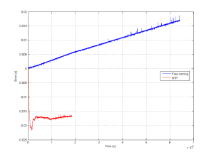
Note that without NTP a typical computer clock will be off by 10 ppm (parts-per-million) or more. This particular one measured about 40 ppm error in free-running mode (no NTP). That means during the duration of this 16e4 s measurement we'd be off by about 640 milliseconds (way off the chart) without NTP. With NTP the error seems to stay within 3 milliseconds or so. The offset of -16 milliseconds is not that accurately measured and could be caused by a number of things.

freerunning_vs_ntp_2013jul26