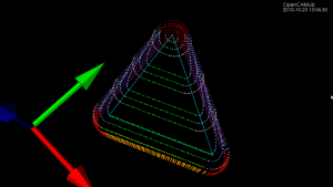
Update: Here is another example with the CL-points coloured differently. At each z-height the innermost loop is with the ball-cutter, next is the bullcutter, and the outermost loop is calculated for a cylindrical cutter. The points are coloured based on which test (vertex, facet, edge) produced them. Vertex-test points are red. Facet-test points are green. The edge-test is further subdivided into (1) a test for horizontal edges (orange), (2) a test for contact with the cylindrical shaft of the cutter (magenta), and (3) the general edge-push function (light blue for ball/bull, pink for cyl). If/when I get the cone-cutter done the cutter-location algorithms in opencamlib should be complete (at least for the moment...), and I can move on to more interesting high-level algorithms.
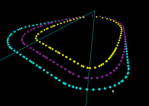
This figure shows one of the first times I got the push-cutter/waterline algorithm working for bullcutter (filleted endmill, bull-nose cutter, toroidal cutter, a dear child has many names...).
The thin cyan lines are edges of a triangle. The outer cyan spheres are valid cutter locations (CL-points) for a cylindrical endmill. The innermost yellow CL-points are for a spherical (or ball-nose) endmill. Between these two point-sets the new development is the magenta points, which are CL-points for a bull-nose cutter.
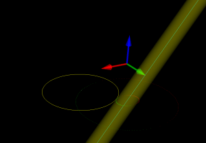
The algorithm works by pushing the cutter at a specified Z-height along either the X-axis or the Y-axis into contact with the triangle. There are three sub-functions for handling the case where the cutter makes contact with a vertex, the triangle facet, and an edge. The edge-contact case is the non-trivial (read "hard") one. The approach I am using is based on the offset-ellipse, courtesy of the freesteel blog. Pushing a toroid into contact with an edge/line is equivalent to pushing the cylindrical "core" of the bullcutter into contact with an edge that has been 'inflated' to a cylinder with a radius equal to the bullcutter corner radius. Slicing this cylinder/tube with a z-plane gives us an ellipse, and the sought cutter-location lies on the offset of this ellipse. I should make some diagrams and post longer/better explanation later (I wonder if anyone reads these 🙂 ).
The bullcutter is important not only in itself, but also because it is the offset of a cylindrical cutter. When we want to do z-terrace roughing with a cylindrical cutter, and specify a stock-to-leave value, we do it by calculating the toolpath with cylcutter->offsetCutter() which is a bullcutter, and then actually machining with the cylindrical cutter. That will achieve the desired stock to leave (to be removed later by a finish operation).


