Lathe tool-post and tools

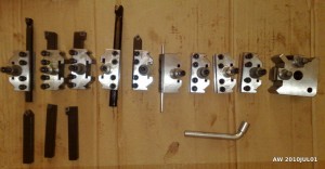
My order from RDG tools arrived today. The quick change tool post if T00, or Myford-size, for 12 or 12.7 mm tools, and included three holders. I also got a pack of five extra holders for a total of eight. There's a set of seven 12mm carbide-insert turning tools, and an internal threading tool for metric (60 degree) threads.

toolpost_and_tools

The order with ER11 and ER25 straight-shank collet chucks including sets of collets from CTC hasn't arrived yet. Since it comes from Hong Kong it will probably go through customs and I will have to pay VAT...

Lathe parting tool

I've ordered a bunch of tooling from RDG (http://www.rdgtools.co.uk/), Chronos (http://www.chronos.ltd.uk/), and CTC (http://www.ctctools.biz/) for the lathe. There's at least one more of these deep-discount tool stores: http://www.arceurotrade.co.uk/. These stores sell tools of mostly Chinese origin, but I think they will do just fine for hobby use, and the price-level certainly is only a fraction of what European tooling costs. If anyone knows more of these let me know!

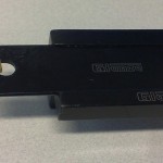
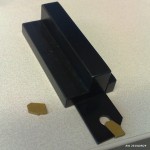
The first things to arrive were a set of center drills and this Glanze parting tool from Chronos. I've settled on only a "Myford-size" T00 tool-post which has holders for max. 13 mm tools.

Lathe chuck

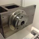
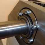
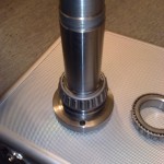
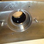
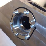
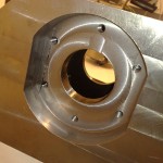
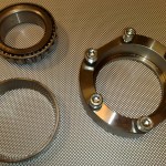
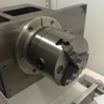
The lathe-project I bought in November is slowly moving forward. I got an Optimum/Quantum 100mm 3-jaw chuck for it today. Turns out the spindle needs to be disassembled to attach the chuck, so this was an opportunity to look at how the spindle is built.

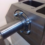
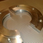
The front bearing seat is machined into the spindle box, while the back bearing seat is a separate bolted on part. The front bearing has a nice 2-part aluminium chip-guard which protects the bearing from coolant and chips. A chip/dust-guard for the back bearing would probably be a good idea too. The spindle is held in place with a nut against the back bearing that tightens the whole assembly. This nut will probably need a set-screw or something else to secure it rigidly (rapid accelerations, changes of direction etc. might otherwise loosen it?). The chuck attaches with three M8 hex bolts, and the 20mm ones which came with the chuck are a bit short - need to buy 3pcs 25mm M8 hex bolts. For now everything is dripping with anti-corrosion spray, but for use the bearings will require either grease or oil (oil is better for higher RPM?). Also, I need to source a timing-belt and 1:1 pulleys to transmit ca 2kW @ 3000-3500RPM from the spindle-servo up to the spindle. Any suggestions?

Wires, wires, wires…

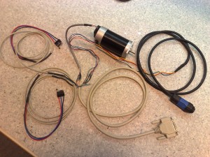
Number of wires from servo-motor to controller on my lathe build: 19.

1: Motor power U
2: Motor power V
3: Motor power W
4: Hall sensor +5V
5: Hall sensor U
6: Hall sensor V
7: Hall sensor W
8: Hall sensor GND
9: Encoder +5V
10: Encoder A
11: Encoder B
12: Encoder Z
13: Encoder GND
14: +Limit switch Common
15: +Limit switch N.O.
16: +Limit switch N.C.
17: -Limit/Home switch Common
18: -Limit/Home switch N.O.
19: -Limit/Home switch N.C.

wires

The motor currents go through the AMP-connecor, everything else through the 25-pin D-connector.

I'm glad the lathe only has two servos (and a spindle), I would go mad with a 5-axis machine...

Connectors

Drilled four holes for AMP-connectors and used a hole-punch to make cut-outs for eight 25-pin D-connectors. The four motor-connectors will provide 3-phase power to the spindle-servo, the X- and Z-servos, and a high-speed live-tool spindle. The servos have three Hall-signals and three(single-ended) or six(differential) encoder signals which will enter the cabinet through the D-connectors. I'm using these since I'll use 25-pin printer-cables for the Hall/Encoder signals. There are eight D-connectors just to provide some room for expansion. Three will be in immediate use for the three servos, one for limit/home switches, and one or two will be used for a jog-pendant.  That still leaves three 25-pin connectors unused (tool-changer? tool-length probe? etc.)

Also mounted the breakout-boards inside:

Lathe Electronics Cabinet


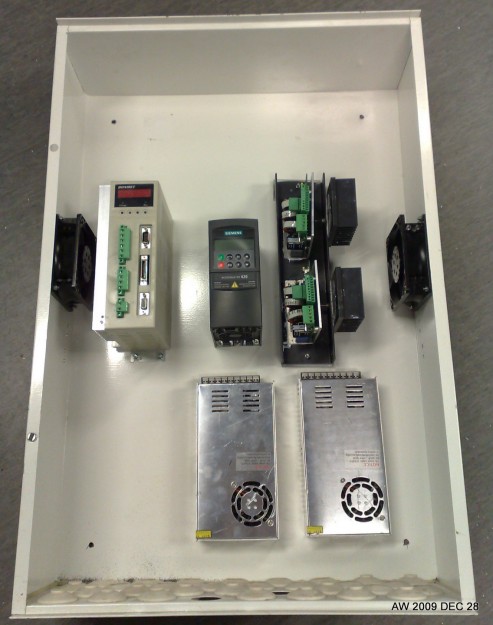
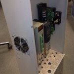
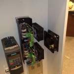
A bit of progress with the electronics cabinet for the lathe. Some components have been bolted to the back wall of the cabinet. From left to right: a Bonmet servo-drive for the main spindle servo, a Siemens VFD for the live-tool spindle motor, and to the right two Brushless PWM amps for the X and Z axis motors from pico-systems. Below these there are two 350W 48VDC switched-mode powersupplies. Today I made holes for two 220VAC 120 mm fans which blow air from both the left and right side into the cabinet directly on the heatsinks of the servo drives. There are plenty of holes in the bottom of the cabinet through which the air can exit.

Lathe electronics

IMG_0764

Most of the electronics I've ordered for the lathe has arrived by now. Still waiting for the servo-drive for the main spindle.

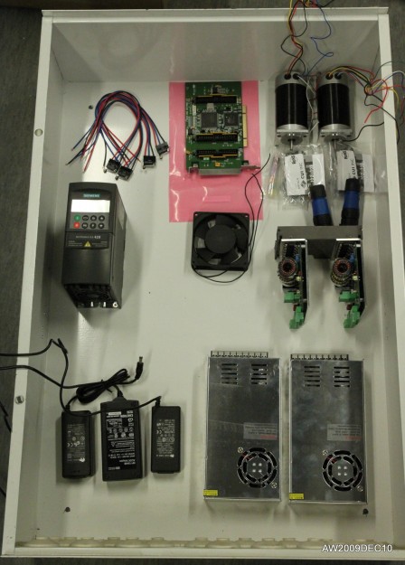
Bottom left are three switched-mode power supplies: 5V 3.5A (logic etc), 12V 3.3A (brushless amps, E-stop chain, etc), 24V 1.3A (spindle brake)

Bottom right are two Chinese 350W 48VDC 7.3A power supplies for the X- and Z- servos. Bought on e-bay from one of the Chinese sellers that has free worldwide shipping, and these were not caught by the local customs, so I paid around 28 euros/supply!

Mid row: on the left a Siemens Micromaster 420 0.37 kW VFD which will be used for a future live-tool spindle, and on the right two pico-systems brushless servo-amps.

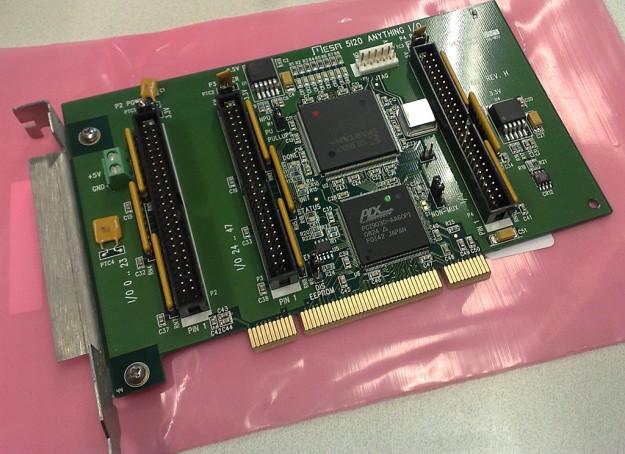
Top: limit switches, Mesa 5I20 PCI-card, 180W Brushless servos for X and Z, CUI encoders, Amphenol connectors.